Service
Troubleshooting
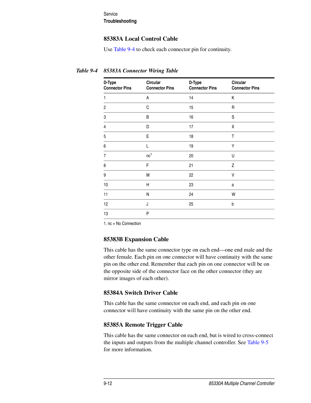
85383A Local Control Cable
Use Table
Table 9-4 85383A Connector Wiring Table
Circular | Circular | ||
Connector Pins | Connector Pins | Connector Pins | Connector Pins |
|
|
|
|
1 | A | 14 | K |
|
|
|
|
2 | C | 15 | R |
|
|
|
|
3 | B | 16 | S |
|
|
|
|
4 | D | 17 | X |
|
|
|
|
5 | E | 18 | T |
|
|
|
|
6 | L | 19 | Y |
|
|
|
|
7 | nc1 | 20 | U |
8 | F | 21 | Z |
|
|
|
|
9 | M | 22 | V |
|
|
|
|
10 | H | 23 | a |
|
|
|
|
11 | N | 24 | W |
|
|
|
|
12 | J | 25 | b |
|
|
|
|
13 | P |
|
|
|
|
|
|
1. nc = No Connection |
|
|
|
85383B Expansion Cable
This cable has the same connector type on each
85384A Switch Driver Cable
This cable has the same connector on each end, and each pin on one connector will have continuity with the same pin on the other end.
85385A Remote Trigger Cable
This cable has the same connector on each end, but is wired to
85330A Multiple Channel Controller |