Agilent B2200A
Manual Part Number
Declaration of Conformity
Herstellerbescheinigung
Manufacturer’s Declaration
Safety Summary
Ground the Instrument
Use extreme caution when handling, testing, and adjusting
Do not Substitute Parts or Modify Instrument
Safety Symbols
CAT
This Manual
Text Conventions
Contents
Front Panel Operation
Programming
Scpi Command Reference
Contents
VXI plug&play Driver
Contents
Error Messages
Introduction
Introduction
Agilent B2200 Series
Front Panel
LCD
Front Panel View
Rear Panel
Rear Panel View
Switch Modules
Switch Module Block Diagram
Specifications
General Specifications
Temperature range Humidity range
Switch Modules
Agilent B2210A/B2211A Switch Module Specifications
Introduction Specifications
Agilent B2200 User’s Guide, Edition
Accessories and Options
Options and Accessories
Model Option Item Description Number
Introduction
Agilent B2200 User’s Guide, Edition
Installation
Installation
Power Cable
Power Requirements
Requirements
Agilent B2200 User’s Guide, Edition
Operating Environment
Storage and Shipping Environment
Inspection
Before Opening Packing Materials
Installing the B2200
To Set the Gpib Address
To Connect the Gpib Cable
To Install the Switch Module
To Install the Blank Panel
Self-Test
Output Connector and Output Signal
Output Connectors
Output Connections
Connector Plates
Connector Plate
Agilent Model No Description
Output Cable
To Make Connections to DUT Interface
Kelvin Output Port Output Port Number
Low-Noise Coaxial Cable
Coaxial Cable Cutting Example
Connector Guard Sense Wire Insulator Plate
Connection to the DUT Interface
Interlock Connector Pin Assignments
To Make Interlock Circuit
To Install LED Circuit
Dimensions of Interlock Switch Agilent part number
When more than ±40 V is forced from an SMU in the 4155/4156
Dimensions of LED Agilent part number
To Mount Connectors
To Check Interlock Circuit
Recommended Parts
Dimensions of Connector Holes
Agilent Part No
Input Connections
B2200 Input Connections Instrument
VMU
CMH/CML
Cable from Connector Plate to DUT
Measurement Cable Length
Input Cable
Probe Card
Guard Capacitances of B2200 Measurement Environment Typical
Cleaning
Maintenance
Calibration
Agilent B2200 User’s Guide, Edition
Front Panel Operation
Front Panel Operation
Operation
About moving cursor, selecting value, and changing display
To Change Channel Configuration Mode
To Enable Light Pen
To Initialize Agilent B2200
To Change Connection Rule
To Control Switch Condition
To Change Connection Sequence
To Open All Switches
To Save/Load Setup Data
To Use Bias Mode
To Use Ground Mode
To Display Firmware Revision
To Use Couple Mode
To Display Module Information
To Set Beeper
To Read Error Message
To Set Gpib Address
To Set Remote Display Mode
To Return to Local Mode
Switch Control Functions
Normal
Channel Configuration Mode
Auto
Connection Rule
Free
Connection Sequence
Connection Sequence Relay Operation
Bias Mode
Example of Bias Mode
Connected to multiple output ports
Ground Mode
Opening the ground enabled input ports
Couple Mode
Input Couple Port Numbers and Output Couple Port Numbers
Couple Port Detection Function
Display Functions
LED Matrix
LED Matrix LED color Explanation
Card 1/2/3/4 LED
LCD
LCD Display Example
LCD Display Items
Label Description
Front Panel Keys
Shift+Local
Function key group
Port Function
Sequence
Gnd Ch
Edit key group
Card Selection
Setup Menus
Setup Menu
Displays the module information of each slot
Config
Error
Selftest Menu
Selftest
KEY
LED
Gpib
Programming
Programming
Scpi Command Hierarchy
Programming Basics
Fundamental Commands
Fundamental Commands Functions
Switch Control
Switch Control Commands Functions
Card No
Channel No
Channel numbers for Auto configuration mode
Programming Examples
Executing the program
Connecting Input-Output Paths
Input-Output Connection Example
Line Description
Using Bias Mode
Bias Mode Example
Agilent B2200 User’s Guide, Edition
Using Ground Mode
Ground Mode Example
Agilent B2200 User’s Guide, Edition
Using Couple Mode
Couple Mode Example
Agilent B2200 User’s Guide, Edition
Saving Input/Output Labels
Label Definition and Data Save Example
Defining Comment for Internal Memory
Memory Comment Definition Example
Capacitance Compensation
Capacitance Compensation Function
Required Conditions
Extension Cables and Compensation Coefficients
To Create Compensation Data File
Pcif
Coefficients to
Module Interfacec Be modified
C2L
Compensation Explanation Coefficients
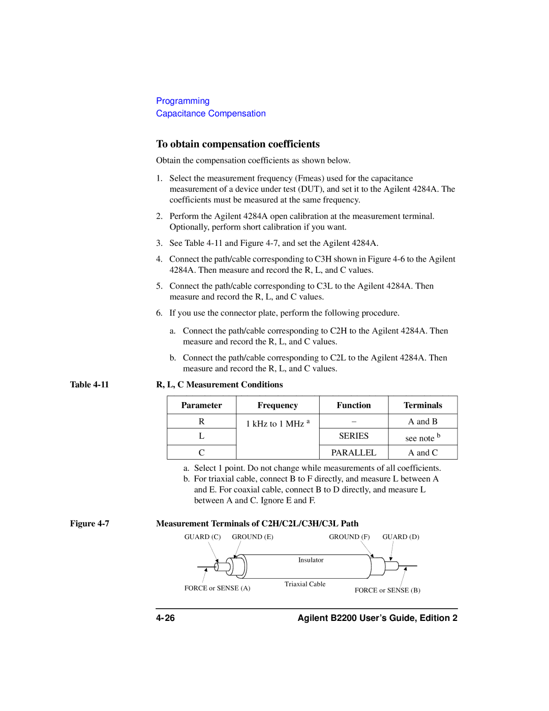
To obtain compensation coefficients
Measurement Terminals of C2H/C2L/C3H/C3L Path
To Perform Measurement and Compensation
Recording Measurement/Compensation Data Step
Capacitance Compensation Program Example
Scpi Command Reference
ROUTe
SYSTem
Textual Notation for Subsystem Commands
Capital Letters
Commands Summary
Common Commands
Mnemonic Name
CLS
Scpi Command Reference *ESR?
Bit Binary-weight Description
IDN?
OPC
Syntax Example
SRE
Parameter Explanation
STB?
TST?
Command Summary
Subsystem Commands
Command Description
Relay Control Commands
Routsymbchan cardnumber,channel,string
Command Description Bias Mode Commands
Routbiasport cardnumber,biasport
Command Description Ground Mode Commands
Routagndport cardnumber,groundport
Couple Mode Commands
Routagndunused cardnumber,enableport
Command Description
System subsystem
Specified by memorynumber
DIAGnosticTESTCARDCLEar
DIAGnosticTESTCARDEXECute?
DIAGnosticTESTCARDSTATe?
DIAGnosticTESTFRAMeCLEar
DIAGnosticTESTFRAMeEXECute?
DIAGnosticTESTFRAMeSTATe?
ROUTeAGNDCHANnelDISableCARD
ROUTeAGNDCHANnelDISableLIST
ROUTeAGNDCHANnelENABleCARD
ROUTeAGNDCHANnelENABleLIST
ROUTeAGNDPORT
ROUTeAGNDSTATe
ROUTeAGNDUNUSED
ROUTeBIASCHANnelDISableCARD
ROUTeBIASCHANnelDISableLIST
ROUTeBIASCHANnelENABleCARD
ROUTeBIASCHANnelENABleLIST
ROUTeBIASPORT
ROUTeBIASPORT
ROUTeBIASSTATe
ROUTeCLOSeCARD?
ROUTeCLOSeLIST
ROUTeCONNectionRULE
Rule
ROUTeCONNectionSEQuence
ROUTeCOUPlePORT
Coupleport
ROUTeCOUPlePORTDETect
ROUTeCOUPleSTATe
ROUTeFUNCtion
ROUTeOPENCARD
ROUTeOPENLIST
ROUTeSYMBolCHANnel
ROUTeSYMBolPORT
SYSTemCCONfig?
SYSTemBEEP
SYSTemCDEScription?
Query response carddescription newlineEND
SYSTemCPON
SYSTemCTYPe?
SYSTemDISPlayLCD
SYSTemDISPlayLED
SYSTemDISPlaySTRing
SYSTemERRor?
SYSTemKLC
SYSTemMEMOryCOMMent
SYSTemMEMOryDELete
SYSTemMEMOryLOAD
SYSTemMEMOrySAVE
SYSTemPEN
SYSTemVERSion?
Status Reporting Structure
Status Reporting Structure
Status Reporting Structure
Status Reporting Structure of B2200
Status Byte Register
Status Byte Register of B2200
Status Byte Register of B2200 Bit Definition Explanation
Service Request Enable Register
Service Request Enable Register of B2200
Standard Event Status Register
Standard Event Status Register of B2200
Standard Event Status Enable Register
Bit Definition Explanation
Output Queue
Output Queue of B2200
VXI plug&play Driver
VXI plug&play Driver
System Requirements
Installing VXIplug&play Driver
Agilent B2200 Driver Function Lists
Driver Functions
Category Function Description
Agilent B2200 User’s Guide, Edition
Agb220xabiasChanCard
Agb220xabiasChanList
Biasdisen
Agb220xabiasChanListQ
Biasstatus
Agb220xabiasPort
Agb220xabiasState
Agb220xacloseCardQ
Agb220xaclose
Closecard
Agb220xacloseList
Agb220xacloseListQ
Agb220xacmd
Closestatus
Cmdstr
Agb220xacmdDataQ
Agb220xacmdInt
Size
Result
Agb220xacmdInt16Q
Agb220xacmdInt16ArrQ
Count
Agb220xacmdInt32ArrQ
Agb220xacmdInt32Q
Agb220xacmdReal
Agb220xacmdReal64ArrQ
Agb220xacmdReal64Q
Agb220xacmdStringQ
Agb220xacompenC
Agb220xaconnRuleSeq
Agb220xacouplePort
Agb220xadcl
Agb220xacoupleState
Agb220xadetectCouplePort
Agb220xaerrormessage
Agb220xaerrorquery
Errornumber
Message
Agb220xaerrorQueryDetect
Agb220xaerrorQueryDetectQ
ErrorQueryDetect
PErrDetect
Channelconfig
Agb220xaesrQ
Agb220xafunc
Errstr
Agb220xagroundChanCard
Agb220xagroundChanList
Gndcardno
Gndchandisen
Gnddisen
Agb220xagroundChanListQ
Gndstatus
Agb220xagroundPort
Agb220xagroundState
Gportcardno
Gndport
Doreset
Agb220xainit
Agb220xaopcQ
InstrDesc
Agb220xaopenList
Agb220xaopenCard
Opencardno
Agb220xaopenListQ
Agb220xareadStatusByteQ
Openstatus
StatusByte
Agb220xarevisionquery
Agb220xareset
Agb220xaselectCompenFile
Agb220xaselftest
Agb220xatestClear
Testresult
Testmessage
Agb220xatimeOut
TimeOut
Agb220xatestExecQ
Execresult
Agb220xatimeOutQ
PTimeOut
Agb220xaunusedPort
Unusedport
Agilent B2200 User’s Guide, Edition
Error Messages
Error Range Error Category
Error Category Standard Event
Standard Scpi Error Messages
Command Error
Data type error
Command header error
Header separator error
Invalid separator
Numeric data error
Character data error
Invalid character in number
Exponent too large
String data error
Block data error
Expression error
Character data not allowed
Execution Error
Device-Dependent Errors
Device-specific error
Memory error
Queue overflow
Query Errors
B2200 Specific Error Messages
B2200 Channel Related Errors
B2200 Card/Mode/Port Related Errors
Cant change to ACONfig mode. Check card config
Too many relays closed. Max 52 relays/card
Cannot use same port for Couple and Bias
Bad auto ground port number
Cannot use Unused Port during Auto Ground Mode on
Bad setting memory number
Setting memory data is invalid
Cannot load this setting data in this configuration