682XXB, 683XXB specifications
The Anritsu 683XXB and 682XXB series are advanced vector network analyzers (VNAs) renowned for their precision and versatility in characterizing RF and microwave components. Designed for engineers and technicians involved in the development, manufacturing, and testing of high-frequency devices, these analyzers offer state-of-the-art technology that ensures optimal performance in various applications.One of the hallmark features of the Anritsu 683XXB and 682XXB is their high dynamic range, which allows for accurate measurements of small reflection and transmission coefficients, essential for assessing the performance of complex RF structures. With frequency coverage extending from DC to 70 GHz, these analyzers cater to a broad spectrum of applications, making them suitable for industries such as telecommunications, aerospace, and automotive.
The user-friendly interface of the Anritsu VNAs is complemented by a high-resolution display, which facilitates easy navigation through measurement setups and results. The analyzers feature multiple measurement modes, including S-parameter measurements, time-domain analysis, and noise figure measurements, providing engineers with comprehensive tools for device characterization.
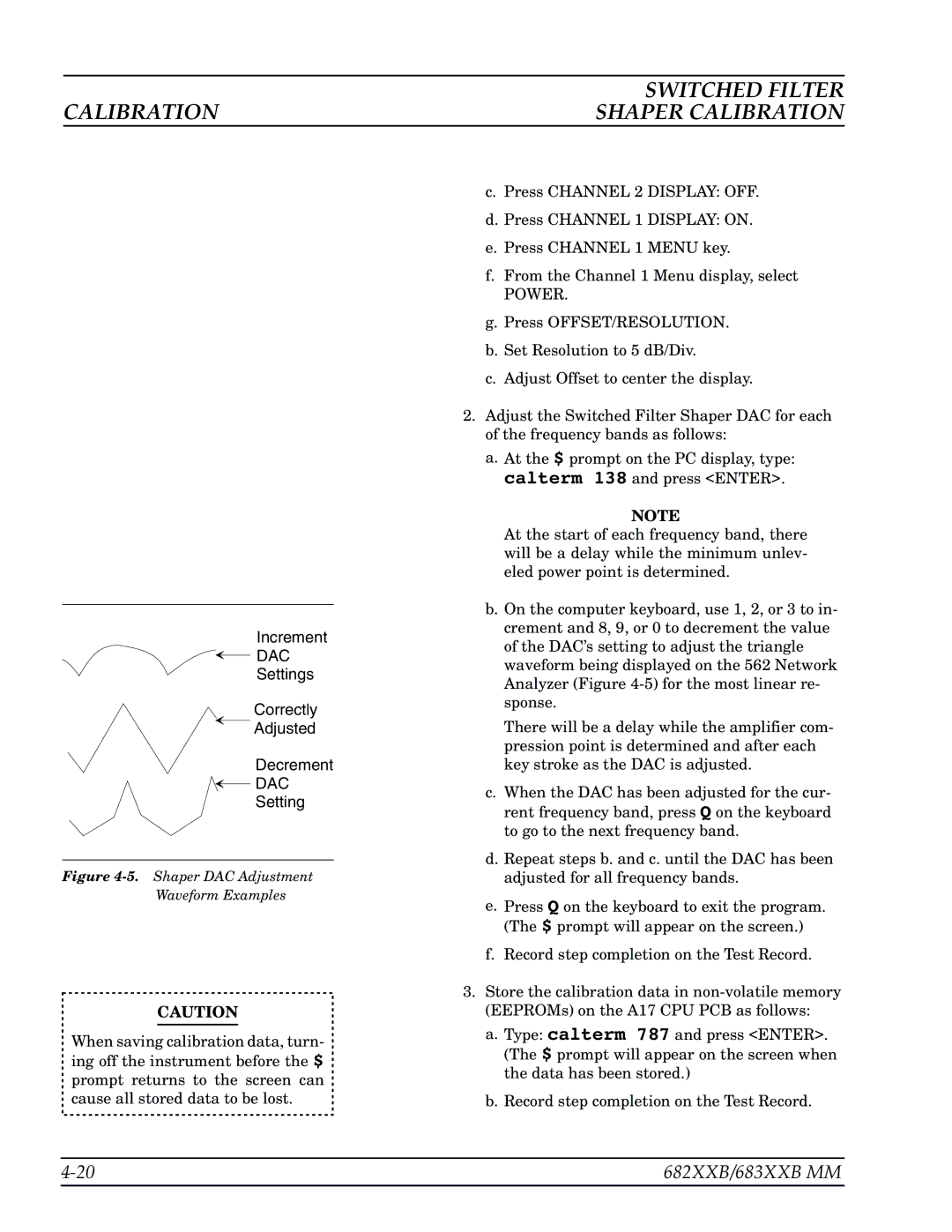
Both the 683XXB and 682XXB implement advanced calibration techniques, including automated calibration and error correction methods, to enhance measurement accuracy. These methods significantly reduce the uncertainties associated with test setups, enabling reliable performance evaluations of components like filters, amplifiers, and antennas.
Anritsu’s proprietary technologies, such as the VectorStar and ShockLine series integration, further empower the 683XXB and 682XXB models. These technologies enable high-throughput testing and improved measurement stability, addressing the needs of modern production environments that demand rapid turnaround times without sacrificing precision.
Additionally, the analyzers come equipped with various connectivity options, including USB, LAN, and GPIB, ensuring seamless integration into automated test systems. This adaptability enhances the analyzers' utility in both laboratory settings and field operations.
In conclusion, the Anritsu 683XXB and 682XXB series vector network analyzers represent the pinnacle of RF and microwave testing technology. With their unmatched precision, comprehensive measurement capabilities, and advanced calibration techniques, these instruments are indispensable tools for professionals striving to push the boundaries of high-frequency device performance and reliability.

