HSIM-W6 USER’S Guide
Page
FCC Notice
Vcci Notice
Exclusion of Warranty and Disclaimer of Liability
Declaration of Conformity
Contents
Isdn Line Ordering and Configuration
HSIM-W6 Configuration with Quickset
Viii HSIM-W6 User’s Guide
MIB Navigator
Troubleshooting
Appendix a Wpim Cable Specifications
Xii HSIM-W6 User’s Guide
Structure of this Guide
Introduction
Related Documents
Following conventions are used throughout this guide
Document Conventions
Your email address
Getting Help
WAN Connection
HSIM-W6 Hardware
About the HSIM-W6
Remote Management Capabilities
Additional Features
Optional Feature
HSIM-W6 Firmware Support
WAN Protocols
About the HSIM-W6
Firmware Data Compression
Inverse Multiplexing
Dhcp and NAT
Hdlc
PAP and Chap Security
Point-to-Point Protocol
Multilink Protocol
LQM
Isdn
Isdn Back-up
Bridging and Routing
Hdsl
About the HSIM-W6
Bridging and Routing Protocol Filtering
System Passwords
MIB IIRFC1213 Rmon MIBRFC1271
Simple Network Management Protocol Snmp
CTISDN-REMOTEPROFILE-MIB
About the HSIM-W6
Software and Firmware Upgrades
Isdn Line Ordering and Configuration
Arranging Isdn Service
Isdn BRI Line Configuration
Telephone Switch Support
SPIDs, Directory Numbers and Telephone Numbers
Isdn BRI Configurations
National Isdn 1 NI-1
Telephone Switch Parameters
AT&T 5ESS with Custom Software
DMS-100
Router a Configuration
Configuration Process and Terminology
Collect Network Information
Names and Passwords
Isdn Line Information
Service Profile Identifications SPIDs
Network Information Layout
Network Information Diagrams
Planning for HSIM-W6 Isdn Configuration
WAN Link
HSIM-W6 to Remote Router Without a Pre-Assigned IP Address
Phone Numbers
Planning for HSIM-W6 Isdn Configuration
Network Information Tables
Configuring System Settings
Remote Router Description Configuration Database
Configuring the Remote Router Database
IP Address, Subnet Mask of the remote
Bridging/Routing Description Configuration Database
Bridging and Routing Controls
Sample Configuration
Sample Network Diagram
FP2
HSIM-W6 Sample Configuration Settings
None
Remote Router FP3
Remote Router ISP Internet Service Provider
Configuration Section Setting Remote RouterDatabase
FP3
Router Names and Passwords
Names and Passwords Example
Unpacking the HSIM-W6
Guidelines for Installations
Installing WAN Port Interface Modules WPIMs
Installing Interface Modules
Wpim
Installing a Wpim
CSX-COMP/ENCR Installation
CSX-COMP/ENCR
Installing an Hsim in an Interface Module
Installing an Hsim
Chapter
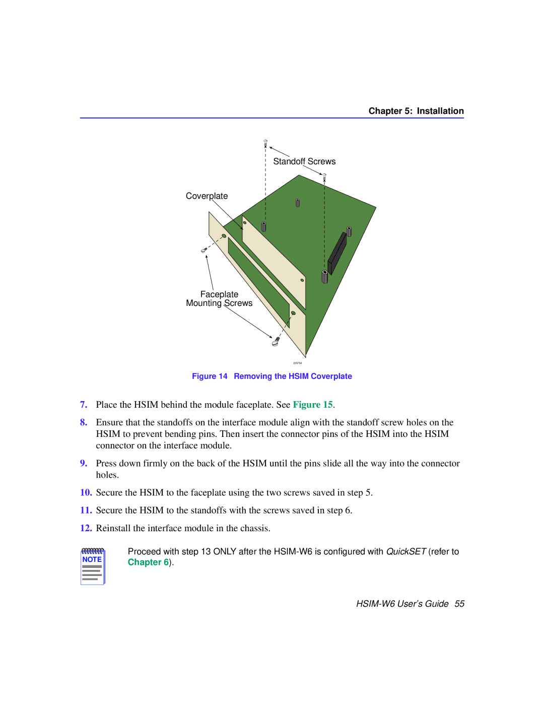
Installing the Hsim
Installing an Hsim in a SmartSWITCH Chassis
Reconnect the chassis to your network
Installation
HSIM-W6 Configuration with QuickSET
HSIM-W6 Configuration with QuickSET
Second Introductory Window
Hsim Configuration
Hsim Configuration Window
Hsim Configuration Window
Secondary IP Address List Window
System Passwords Window
HSIM-W6 Configuration with QuickSET
Wide Area 1 and 2 Configuration
Wide Area T1 Configuration Window
Wide Area T1 Configuration Window
Telco Configuration Information
HSIM-W6 Configuration with QuickSET
Wide Area E1 Configuration Window
Wide Area E1 Configuration Window
Telco Configuration Information
Wide Area DI Configuration Window
Wide Area DI Configuration Window
HSIM-W6 Configuration with QuickSET
HSIM-W6 Configuration with QuickSET
Wide Area Synchronous WAN Configuration Window
Wide Area Synchronous Configuration Window
Sync Port Type Interface Cable Type Cabletron Part Number
Sync Port Types
HSIM-W6 Configuration with QuickSET
Wide Area DDS Configuration Window
Wide Area DDS Configuration Window
Telco Configuration Information
Wide Area Hdsl Configuration Window
Wide Area Hdsl Configuration Window
Hdsl Transmit Clock Source Slave or Master
Wide Area Frame Relay Time Slot Configuration Window
Wide Area Frame Relay Time Slot Configuration Window
HSIM-W6 Configuration with QuickSET
Wide Area PPP Time Slot Configuration Window
Wide Area PPP Time Slot Configuration Window
HSIM-W6 Configuration with QuickSET
Wide Area Hdsl Time Slot Configuration Window
Wide Area Hdsl Time Slot Configuration Window
HSIM-W6 Configuration with QuickSET
Bridging and Routing Configuration Window
Bridging and Routing Configuration
Firewall Configuration Window
Firewall Configuration Window
HSIM-W6 Configuration with QuickSET
TCP Services Port #
TCP Services Port Numbers
UDP Service Port #
UDP Services Port Numbers
Bridging and Routing WAN Frame Type Configuration Window
WAN Frame Type Configuration Window
Routing Configuration Window
Routing Configuration Window
IPX Routing Configuration
IP Routing Configuration
Host Map Window
HSIM-W6 Configuration with QuickSET
Advanced Routing Configuration Window
Advanced Routing Configuration Window
Advanced IP Routing Settings
Dhcp Settings Configuration Window
HSIM-W6 Configuration with QuickSET
NAT Settings Configuration Window
Delete Proxy... Allows you to delete NAT proxy servers
File Menu
QuickSET Pull-Down Menus
Store Configuration Window
Firmware Upgrade Menu
TFTP/BootP Services Window
110 HSIM-W6 User’s Guide
Advanced Configuration Menu
Advanced Configuration Menu
Compression & Congestion Window
Compression & Congestion Window
HSIM-W6 Configuration with QuickSET
114 HSIM-W6 User’s Guide
Chapter Organization
General Configuration Using Local Management
Local Management Overview
Management Agent
Local vs. Remote Management
Sample Local Management Screen
Local Management Screen Elements
Message Meaning
Event Messages
Keyboard Conventions
Local Management Keyboard Conventions
Navigating Within Local Management Screens
Accessing Local Management
Local Management Screen Hierarchy
Establishing a Telnet Connection
HSIM-W6 Password Screen
Using the Menu Screens
Main Menu Screen
Main Menu Screen
Setup Menu Screen
Setup Menu Screen
General Configuration Using Local Management
System Level Screen
System Level Screen
General Configuration Using Local Management
Setting the System Time
Setting the System Date
Setting the Subnet Mask
Setting the Host IP Address
Setting the Default Interface
Setting the Default Gateway
Snmp Community Names Screen
Snmp Community Names Screen
Setting Snmp Community Names
Community Name Access Policy
Trap Table Screen Fields
Snmp Traps Screen
Setting the Snmp Trap Destination
Flash Download Screen
Flash Download Screen
Selecting a Flash Download Method
Runtime Download
138 HSIM-W6 User’s Guide
Bridge Setup Screen Fields
Bridge Setup Screen
Selecting a Spanning Tree Protocol
Selecting the Bridge Port Administrative Status
Bridge Port Pair Admin Status Port 01 - Port 02 Disabled
Selecting the Bridge Port Pair Administrative Status
Router Setup Screen Fields
Router Setup Screen
IP Configuration Screen Fields
IP Configuration Screen
IP General Configuration Status Fields
IP General Config Screen
IP General Configuration Fields
Selecting a Port for Configuration
Selecting the Frame Type for a Port
UDP Port Numbers
UDP Port # UDP Services
Enabling Proxy ARP on a Port
Configuring the Network Broadcast Type on a Port
Enabling the RIP on a Port
152 HSIM-W6 User’s Guide
IPX Configuration Fields
IPX Configuration Screen
154 HSIM-W6 User’s Guide
IPX General Configuration Status Fields
IPX General Configuration Screen
IPX General Configuration Fields
Entering the IPX Address
Enabling IPX Routing Services on a Port
IPX Routing over Frame Relay
Circuitmap Command
Enabling the IPX SAP Protocol on a Port
IPX SAP Configuration Screen
162 HSIM-W6 User’s Guide
IPX RIP Setup Screen
WAN Physical Configuration Screen
WAN Setup
WAN Physical Configuration Screen Fields
WAN Interface Configuration Screen Fields
WAN Interface Configuration Screen
General Configuration Using Local Management
168 HSIM-W6 User’s Guide
MIB Navigator
Managing Device MIBs
MIB Navigator Screen
Hierarchical MIB Tree Structure
MIB Navigator Command Set Overview
Conventions for MIB Navigator Commands
Navigation Commands
Command
Branch
Ctron
Mib2
Help
Pwd
Next
Set
Snmp Community Names Screen section in for more
Whoami
Tree
Dir
Grep
Get
Arp
Other Commands
Defroute
Winsaddress Domainname The Ifnum is the Ethernet
Dhcp
Nat
Nat command provides status relating to Network Address
Nat
Ping
Netstat
Snmpget
Snmpbranch
Snmpset
Traceroute
Snmptree
Circuitmap
Bridge
Ppp
Reset
SecondIP
Route
Snmpnext
Show
Dc Groupid Interfacenum Deletes the WAN channel
Imux
Done, quit, exit
Special Commands
Troubleshooting
HSIM-W6 Async Console Connection Pinout
HSIM-W6 Async LED States Console Connection Only
HSIM-W6 WAN Link LNK LED States
HSIM-W6 Async Modem Connection Pinout
HSIM-W6 WAN Status STS LED States for T1, DI, and E1 Ports
HSIM-W6 WAN Status STS LED States for DDS Ports
HSIM-W6 WAN Status STS LED States for Sync Ports
Power PWR LED is OFF
Troubleshooting HSIM-W6 Hardware
Processor CPU LED is OFF
HSIM-W6 WAN Status STS LED States for Hdsl Ports
Async Console Connection
Troubleshooting the WAN
Status STS LED is Amber Blinking
Link LNK LED is RED
WPIM-T1, WPIM-E1, WPIM-DI, or WPIM-DDS Installed in HSIM-W6
Status STS LED is RED
Status STS LED is Green
Investigating Software Configuration Problems
Connection to Device Fails During Software Configuration
User Cannot Communicate with Remote Network Station
208 HSIM-W6 User’s Guide
1 Interface Cable Part Numbers
1 Connector Pin Assignments
Network Pin Assignments
DTE Pin Assignments
WPIM-SY Interface Cables
WPIM-SY
EIA-449
EIA-449 Interface
EIA-449 Interface Cable Pin Assignment
35 Interface Cable Pin Assignment
35 Interface
214 HSIM-W6 User’s Guide
EIA-232
EIA-232 Interface
EIA-232 Interface Cable Pin Assignment
21 Interface Cable Pin Assignment
21 Interface
EIA-530, EIA-530 ALT A, EIA-530 A, and EIA-530 a ALT a
218 HSIM-W6 User’s Guide
Network Pinout Assignments
DDS Interface Cable Part Number
Network Interface
WPIM-E1 Connector Information
DTE Interface
Provides WPIM-E1 DTE interface cable pin assignments
WPIM-DI Network
WPIM-DI Connector Information
WPIM-HDSL Network Interface Cable Pin Assignments
WPIM-DI Drop and Insert
WPIM-S/T Network Interface Cable Pin Assignments
WPIM-S/T
Hardware Specifications
Regulatory Compliance
WPIM-TI
Individual Wpim Regulatory Compliance
WPIM-DDS
WPIM-S/T
Remote Router
Network Information Worksheets
Chapter C Network Information Worksheets
WPIM-DI and WPIM-T1
WPIM-DDS Only
WPIM-S/T Only
Chapter D FCC Part 68 User’s Information For HSIM-W6
Chapter D FCC Part 68 User’s Information For HSIM-W6
My commission expires
Glossary
Chapter E Glossary
HSIM-W6 User’s Guide237
Chapter E Glossary
HSIM-W6 User’s Guide239
Chapter E Glossary
Index
Index
UDP
Index