Corporate Headquarters
Copyright 2001, Cisco Systems, Inc All rights reserved
Document Information
General Information
Mailing Information
Business Reply Mail
N T E N T S
Cell Bus
Module Requirements with Bulk Distribution and Redundancy
Wiring a Mixed Ground System with Redundant Supplies
Other Ports
Configuring Logical Interfaces for the Feeder
Card and Service Configuration
Features
Technical Specifications
FRSM-2CT3 Framer
ATM UNI
Xiv
G U R E S
Figure B-1
B L E S
Table A-1
Table A-33
Release 1.1.31, Part Number 78-11215-03 Rev. B0, May
Organization
Audience
This document is organized into the following chapters
Related Documentation
Documentation Description
Cisco WAN Manager, Release 10, Related Documentation
Conventions
Xxiv
Obtaining Documentation
World Wide Web
Documentation CD-ROM
Ordering Documentation
To access Cisco.com, go to the following website
Obtaining Technical Assistance
Documentation Feedback
Cisco.com
Technical Assistance Center
Contacting TAC by Using the Cisco TAC Website
Contacting TAC by Telephone
Xxviii
Introducing the MGX
A P T E R
MGX 8230 System Overview
MGX 8230 with Door Attached
Applications of the MGX
Universal Edge Architecture
Slot Numbering and Placement
MGX 8230 Enclosure and Power
Standards-Based Conversion to ATM
Single Height and Double Height Slots
PXM
MGX 8230 Power System
Optional AC Power Supply
DC-Powered MGX
AC Power Supply Module, Rear View
MGX 8230 DC Power Entry Module
Cooling System
MGX 8230 Fan Tray Assembly
MGX 8230 Architecture
Cell Bus
PXM-UI
MGX 8230 Management
Cell Bus Distribution
Processor Switching Module PXM1
Introduction to Core Card Sets and Service Modules
Summary of MGX 8230 Cards and Modules
MGX-BNC-2T3
User Interface Back Cards
MGX-BNC-2E3
Frame Relay Service Modules Frsm
Service Resource Module SRM
ATM UNI Service Modules Ausm
Voice Service Modules Vism
Circuit Emulation Service Modules Cesm
Route Processor Module RPM
Redundancy for Service Modules
Redundancy
Hot Standby
1N Redundancy
Introducing the MGX Summary of MGX 8230 Cards and Modules
Release 1.1.31, Part Number 78-11215-03 Rev. B0, May
Module and Service Descriptions
Processor Switching Module
PXM1 Features
PXM1 Illustration and LED Description
PXM1 User Interface Back Cards
PXM1-UI standard
Maintenance, Control and LAN ports
Making External Clock Connections
PXM-UI-S3 optional
Stratum 4 clocking
PXM1 Back Cards
PXM1 User Interface Back Cards
Alarm Output Connection
User Interface Back Card PXM-UI-S3 Stratum 3 Clocking
SMFLR-1-622 Back Card
OC-12 Long-Reach Back Card SMFLR-1-622/B
SMFIR-1-622 Back Card
OC-12 Intermediate-Reach Back Card SMFIR-1-622/B
SMF-155 Back Card
OC-3 Four-Port Back Card SMF-155/B
BNC-2T3 Back Card
Two-port T3 Back Card BNC-2T3
BNC-2E3 Back Card
Two-port E3 Back Card BNC-2E3
Service Resource Module
Bit Error Rate Testing
1N Service Module Redundancy
Bulk Distribution Mode
Installation Requirements for the MGX-SRM-3T3/C
SRM Illustration and LED Indicators
Module Requirements with Bulk Distribution and Redundancy
Type of LED Color Meaning
MGX-SRM-3T3/C Card Set
ATM UNI Service Module Ausm
Ausm Features
Quality of Service QoS Management
Inverse Multiplexing
Physical Layer Features
All Cards
T1 Cards
E1 Cards
Ausm Front Card Illustration and LED Description
10 AUSM/B-8T1 or AUSM/B-8E1 Front Card
Back Cards for the AUSM/B
Type of LED Color Description
11 RJ-48 and SMB Back Cards for the MGX-AUSM-8T1E1/B
Frame Relay Service Modules
Features Common to All FRSMs
Data-Link Layer features
Frame Relay features
ATM Funi features
Frame Forwarding Features
Redundancy for Frame Service Modules
Connection Types on the Frsm
Congestion Indication for NIW Connections
Frame Relay-to-ATM Network Interworking
Congestion Indication
PVC Status Management
Frame Relay-to-ATM Service Interworking
Efci is always set to
Cell Loss Priority
Command and Response Mapping
Frame Forwarding
ATM Frame-to-User Network Interface
Translation and Transparent Modes
Types of Frame Service Modules
Frsm for T1 features
FRSMs for T1 and E1 Lines
There are three types of FRSMs
Frsm for E1 features
LED Indicators
ACT LED
Stby LED
Card Illustrations
14 MGX-FRSM-8T1
15 RJ-48 and SMB Back Cards for the MGX-FRSM-8T1/E1
Features
FRSMs for T3 and E3 lines
FRSM-2T3E3 LED Indicators
6and -7describe the FRSM-2T3E3 LED faceplate indicators
Card Combinations
Illustrations
16 MGX-FRSM-2CT3
17 MGX-FRSM-2T3E3
18 BNC-2T3
19 BNC-2E3
FRSMs for Serial Connections
FRSM-HS1/B X.21 and V.35 Interfaces
FRSM-HS2 Hssi Interfaces
For the MGX-FRSM-HS2 front card, see -20 on
Mode Type of Cable Clock Source Mode of Far End
MGX-FRSM-HS1/B Cabling
Cable Type
DCE
Dtest DTE
Type of Cable Far End Connector Part Number
DTE-DCE
20 MGX-FRSM-HS2
21 MGX-FRSM-HS1/B Front Card Faceplate
22 SCSI2-2HSSI
23 12IN1 S4 Back Card Faceplate
Cesm T1 and E1 Features
Circuit Emulation Service Modules
Cesm for T1 and E1 lines
LED Indicators for the Eight-Port Cesm
1N Redundancy for the Cesm T1/E1
Cesm T1/E1 Illustrations
AX-SMB-8E1-LM
Fail LED
24 Front Cards for the Eight-Port Cesm
25 RJ-48 and SMB Back Cards for the MGX-CESM-8T1E1
Cesm for T3 and E3 lines
CESM-T3/E3 Features
T3 Interfaces
E3 Interfaces
Cesm T3/E3 Illustrations
MGX-CESM-T3/E3 front card is shown in -26 on
27 BNC-2T3 Back Card for the CESM-T3/E3
28 BNC-2E3 Back Card for the CESM-T3/E3
Summary of Features Supported with Vism
Voice Service The Vism
Vism Documentation
T3 Interfaces via SRM Bulk Distribution
Vism Redundancy
Card Combinations
Vism Card Illustrations and LED Description
29 Vism Front Cards
30 Vism Back Cards
Route Processor Module RPM
RPM Documentation
Release 1.1.31, Part Number 78-11215-03 Rev. B0, May
Site Preparation
Parts Checklist
Environment Operating environment should be as follows
Site Preparation
Maintaining Safety with Electricity
Regulatory Compliance and Safety Information
Safety Recommendations
Site Preparation Maintaining Safety with Electricity
Product Disposal Warning
Site Preparation Maintaining Safety with Electricity
Lightning Activity Warning
Jewelry Removal Warning
Power Supply Warning
Power Supply Disconnection Warning
Power Disconnection Warning
Installation Warning
Grounded Equipment Warning
Laser Beam Warning
Class 1 Laser Product Warning
Seismic Considerations
Seismic Anchoring for a Cisco Rack
Stability Plate Dimensions
Installing a Cisco Cabinet Over the Stability Plate
Power and Grounding
AC Power Circuit Breakers
DC Power Circuit Breakers
Electrical Power for AC-Powered Nodes
Wiring a Mixed Ground System with Redundant Supplies
Bonding and Grounding
Connection Description
DC Current Distance in Feet
Using the Electrostatic Wrist Strap
Co-Locating Cisco Units in the Same Rack
Making the Frame Bonding Ground Connection
Gauge Ohms per 1000 Feet
Making Cisco Cabinet Ground Connections
Frame Bonding Connection in Cisco-Supplied Rack
Release 1.1.31, Part Number 78-11215-03 Rev. B0, May
Chapter Summary
Mechanical Lift Guidelines
If the switch is a stand-alone unit, proceed directly to
Installing a Stand-Alone MGX
Rack Mounting an MGX
Bracket Placement
Prepare for Rack Installation
Rack Positioning
Mounting Kits
17273
Rack Mounting Procedures for 19-Inch Racks Mechanical Lift
Install the MGX 8230 Using a Mechanical Lift Recommended
Rack Mounting Procedures for 23-Inch Racks Mechanical Lift
Install the MGX 8230 Without a Mechanical Lift Optional
Prepare for Installation
Remove the Front Cards
To remove a front card
Remove the Back Cards
Rack Mount the MGX 8230 chassis
Inch rack mounting
Follow these steps to mount an MGX 8230 in a 19-inch rack
Front View of MGX 8230 with 23-Inch Mid-Mounting Brackets
Re-install the front cards
Re-install the back cards
Connecting Power for DC Systems
Rear View of MGX 8230 with Two DC PEMs
Rear View of MGX 8230 with 1 DC PEM
DC PEM
Polarities at MGX 8230 PEM Pluggable Terminal Block
Connecting Power for AC Systems
11 Optional 1200 Watt AC Power Supply Module, Rear View
Making the Connections to the AC Power Supply Modules
23825
Install the Cable Manager
13 Rear View of MGX 8230 with One AC Power Supply Module
Power up the MGX
14 Cable Management System on Rack-Mount MGX
Configuring the MGX 8230 as an BPX Feeder
Release 1.1.31, Part Number 78-11215-03 Rev. B0, May
Summary of Shelf-Level Tasks
Word bay refers to the upper or lower half of the enclosure
User Interface Access Ports
Ethernet port Maintenance port
Control Port
Ethernet Port
Maintenance Port
MGX 8230 MGX to BPX Feeder
Initial MGX 8230 Bring-Up
Other Ports
Bringing Up an MGX 8230 PXM With No Run-time Firmware
Inet on ethernet e 188.29.37.14ffffff00
Bin
Resource Partitioning
Configuring Node-Level Parameters
Enter the following
Procedure
Nodename.1.slot.cardtype.a
Adduser userId accessLevel
Cnfpasswd username
$tftp IP address
Downloading Firmware to a Service Module
Then
MGX 8230 CLI Configuration of a Feeder
Configuring the OC-3 Uplink
Commands are cnfport, dspports, and delport
Addport portnum linenum pctbw minvpi maxvpi
Establishing the BPX 8600-to-BPX 8600 Series Segment
Cnfifastrk slot.port trunk
CiscoView Configuration of a Feeder
Selecting an MGX
Specifying the Feeder Application
Activating a Physical Line for the Uplink
Configuring Logical Interfaces for the Feeder
Configuring the Line as a Feeder Trunk
Partitioning Resources on the Broadband Interface
Connections on a Feeder
Modifying the Resource Partitioning
Rules for Adding Connections
Sequence of Configuration Tasks
Rules for Adding a DAX Connection
Rules for Adding Three-Segment Connections
Frame Relay Connection Through an MGX 8230/BPX Network
Configuring Synchronization for the Shelf
Clock Sources
Clock Source Configuration
Configuration Example
Clock Source Types
Clock types are primary, secondary, and tertiary
Configuring PXM1 Card-Level Parameters, Lines, and Ports
For an internal clock source
Cnfextclk ClockType Impedance
Cnfcdrscprtn numberPARconns numberPNNIconns numberTAGconns
Cnfatmln linenum type
APS Configuration
Automatic Protection Switching on the PXM1
APS Requirements
Adding Connections on a PXM1 in a Stand-Alone Node
Cnfcon connID routepriority maxcost restricttrunktype CAC
ATM Forum TM spec PCR Flow
VBR.3
PolType =3
PolType =4
PolType =5
ATM Universal Service Module Ausm
Summary of Ausm Features
Configure the Card, Lines, and Ports
Cnfportq portnum qnum qalgo qdepth clphigh clplow efcithres
=CBR =VBR =ABR =UBR
Adding and Configuring Connections on the AUSM/B
Configure Inverse Multiplexing
Addimagrp groupnum porttype listoflinks minNumLink
Port number is in the range
Release 1.1.31, Part Number 78-11215-03 Rev. B0, May
Cnfchanfst port.vpi.vci enable fgcraenable ibs pcr mcr icr
Release 1.1.31, Part Number 78-11215-03 Rev. B0, May
Variable Description Value range Default value
If necessary, change the queue depths by using cnfchanq
Frame Service Module Features
BPX 8600-to-BPX 8600 Segment
Summary of Frame Service Module Features
MGX-FRSM-2CT3 Features
MGX-FRSM-2T3E3 Features
MGX-FRSM-HS2 Features
MGX-FRSM-HS1/B Features
Configuring Frame Relay Service
Eight-Port Frsm Features
Cnfln linenum linetype linerate
Configuring the Frsm Cards, Lines, and Ports
Correspond to Line Rates in Kbps
Addport portnum linenum porttype
Addport portnum linenum ds0speed beginslot numslot porttype
Addport portnum porttype
Cnfport portnum lmisig asyn elmi T391 T392 N391 N392 N393
Adding a Frame Relay Connection
Release 1.1.31, Part Number 78-11215-03 Rev. B0, May
Service Type Default EgressQueue PXM1 Service Type
Cnfchanmap channum chanType FECN/EFCI DE to CLP CLP to DE
CIR
Test Commands for the FRSMs
Establishing the BPX 8600-to-BPX 8600 Series Segment
Support for Alarm Reporting
Bit Error Rate Testing on an Unchannelized T3 or E3 Frsm
Features
Circuit Emulation Service Module for T3 and E3
Cell Delay Treatment
Configuring Service on a T3 or E3 Cesm
Error and Alarm Response
Alarm Down Error Type Stream Up Stream Comments
AIS-OAM
Configuring the Card, Lines, and Ports
Adding and Modifying Connections
Addcon portnum mastership remoteConnId
Cnfcon portnum Cdvt CellLossIntegPeriod bufsize
Eight-Port Circuit Emulation Service Modules
Bit Error Rate Testing on a T3 or E3 Cesm
Structured Data Transfer
Unstructured Data Transfer
Error and Alarm Response
Cell Delay Treatment
Redundancy Support for the Eight-Port Cesm
Configuring Service on an Eight-Port Cesm
Cnfln linenum linecode linelen clksrc E1-signalling
Receive LOF Receive AIS Blue AIS AIS link
AIS over the T1 link or alternating 1s
Configuring Bulk Distribution and Redundancy
Addport portnum linenum beginslot numslot porttype
Execute addred
Release 1.1.31, Part Number 78-11215-03 Rev. B0, May
Configuring Card and Line Parameters
T1Slot T1 slot number, in the range
Bulk Distribution for T1 Service
NumberOfT1s Number of T1s, in the range
Configuring Redundancy Through the Redundancy Bus
Redundancy Support by the MGX-SRM-3T3/C
Configuring Redundancy Through the Distribution Bus
RedType Is a number that specifies the type of redundancy
Bit Error Rate Testing Through an MGX-SRM-3T3
Test Medium Medium Type Device to Loop Bert Pattern
Test Medium Medium Type Loopback
Port Any None All patterns Line Metallic
Port Any Remote loopback Line Metallic or remote
Pattern Test Options
Line Far end, remote, or Metallic
Line None All patterns
Line Remote or metallic
Online Diagnostics test
Automatic Switchover
Alarms
Loopback Test Options
Commands to Operate the Online Diagnostics
Oldiags debuglevel switchenable
Log Files
Oldiags-help or oldiags help
Configure Loopback on the Entire DS3 Line
DS3 Loopback Test
Loopback Tests
Oldsplog logname
Receive a Loopback Request
Configure Loopback on All DS1s in a DS3 Line
To verify that DS3 interface can be put into loopback
Configure DS3 for Sending Looped or Normal Data
Configure Transmit Feac Code
Configure DS3 to Send Line Loopback
Configure Receive Validation Feac Code
Configure DS3 for Sending Loopback Deactivation Request
Configuring Feac Validation Criteria to be FEACCodes4Of5
Dspln should show LineXmtFEACCode as SendResetCode
Disable Feac Codes
Configure Feac Validation Criteria to be FEACCodes8Of10
Negative Tests
Configure DS3 Loopback Codes from the Standby PXM1 Card
Card and Service Configuration DS3 Loopback Test
Technical Specifications
Frsm HS1/B Specifications
Value
MGX 8230 Processor Switching Module Specifications
Category Description
LED
Category Description
ESD
AUSM/B-8T1E1 Interface Characteristics
IEC
LOS, OOF, AIS, RAI
LCV, LES, LSES, CV, ES, MGX 8230, SEFS, AISS, UAS
LM-SMB-8E1
CBR, VBR, VBR+
ATMizer Channel Counters
Counter Type Description
Other Counters
FRSM-2CT3 Specifications
Feature Significance or Value
Interface Standard
B3ZS
FRSM-2T3E3 Specifications
FRSM-2CT3 Line Alarms
FRSM-2CT3 Framer
Interoperability Implementation Agreement v
FRSM-2T3E3 T3 Line
T3 line characteristics appear in Table A-13
T3 Framer Level
FRSM-HS2 Specifications
FRSM-2T3E3 Line Alarms
Statistics and Counter Specifications
FRSM-2T3E3 E3 Line
Number of Hssi Lines Two Connector Type
SCSI-2
Service Statistic
Counter
ATM Cell Statistic
Diagnostic Statistic
Troubleshooting Statistic
Interfaces
ECN current queue depth, per channel
FRSM-8T1 Specification
FR/ATM PVC Interworking Implementation Agreement FRF.5
Table A-26 List of Counters
FRSM-8E1 Specification
Table A-28 Frame Relay Service With E1 Lines
Diagnostics per port Last unknown Dlci that arrived
Transmit frames s
Changes
FR/ATM PVC Interworking Implementation Agreement FERF.5
Table A-30 List of Counters
Circuit Emulation Service Module for T1 Operation
B8ZS
Circuit Emulation Service Module for E1 Operation
Category
Transmit Clocking Normal clock or Srts generated Line Coding
Physical and Electrical Characteristics for Cards
Electromagnetic Compatibility
Nebs
Conformance
EMC
Frame Relay
Circuit Emulations Service
ATM Forum CES
Safety
Environmental
Connector Description
T3 Trunk Cabling
Cable Parameter Description
Rx BNC Receive T3 from trunk Tx BNC Transmit T3 to trunk
T1 Cabling
Frame Relay Cabling
Pin No Description
E1 Cabling
SMB Connector
Rx BNC Receive E1 from trunk Tx BNC Transmit E1 to trunk
Signal Name Source
12IN1-S4 V.35/X.21 Back Card
Signal Name
Hssi Port Connectors
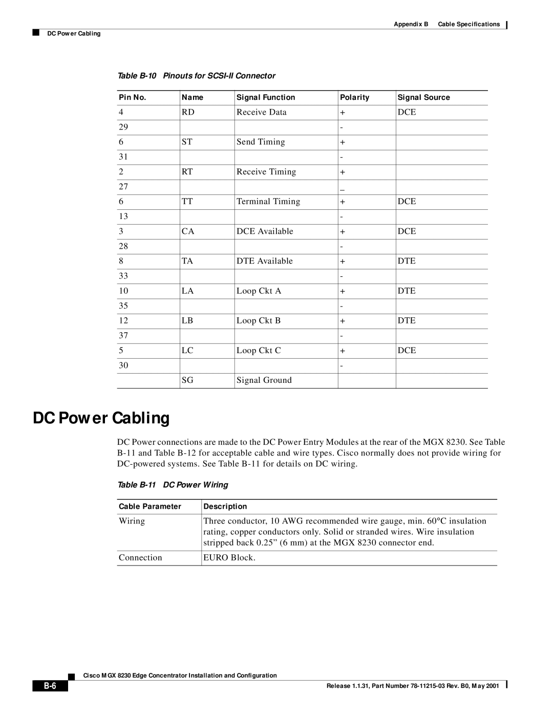
Pin No Name Signal Function Polarity Signal Source
DC Power Cabling
Maintenance and Control Ports
AC Power Cabling
Control and Clock Cabling
External Alarm Cabling
External Clock Input Cabling
T1 Clock Cabling
Pin No Name Description
Pin No Alarm Description
Release 1.1.31, Part Number 78-11215-03 Rev. B0, May
Monarch chip set
More general Class of Service Buffer or CosB
StrataView Plus
StrataCom IGX switch
GL-2
GL-3
Strictly correct
AAL5
APS
Ausm
AUSM/B
Frsm cards Circuit Emulation Service Module
Cesm
CIR
AX-CESM-8E1 AX-CESM-8T1
Frsm
MGX-HS2/B Front cards
MGX-FRSM-2E3T3
MGX-AUSM/B-8E1
MGX-AUSM/B-8T1
MGX-FRSM-2CT3
MGX-HS2/B
PAR
PXM
PXM1-UI
PXM-UI
Sonet
SRM-3T3