Centronics Parallel Pinout Information |
|
|
|
|
|
|
|
|
|
|
|
|
| ||||
|
|
|
|
|
|
|
|
|
|
|
|
|
|
|
|
| Data 7 |
|
|
|
|
|
|
|
|
|
|
|
|
|
|
|
|
| Data 6 |
Acknowledge (ACK) |
|
|
|
|
|
|
|
|
|
|
|
|
|
|
|
| Data 5 |
|
|
|
|
|
|
|
|
|
|
|
|
|
|
|
| Data 4 | |
Busy |
|
|
|
|
|
|
|
|
|
|
|
|
|
|
|
| Data 3 |
Paper Error (PE) |
|
|
|
|
|
|
|
|
|
|
|
|
|
|
|
| Data 2 |
Ready |
|
|
|
|
|
|
|
|
|
|
|
|
|
|
|
| Data 1 |
Signal Ground |
|
|
|
|
|
|
|
|
|
|
|
|
|
|
|
| Data 0 |
Chassis Ground |
|
|
|
|
|
|
|
|
|
|
|
|
|
|
|
| Strobe (STR) |
+5V |
|
|
|
|
|
|
|
|
|
|
|
|
|
|
|
|
|
18 | 17 | 16 | 15 | 14 | 13 | 12 | 11 | 10 | 9 | 8 | 7 | 6 | 5 | 4 | 3 | 2 | 1 |
36 | 35 | 34 | 33 | 32 | 31 | 30 | 29 | 28 | 27 | 26 | 25 | 24 | 23 | 22 | 21 | 20 | 19 |
Error (ERR)
Reset/Input Clear
Ground |
|
|
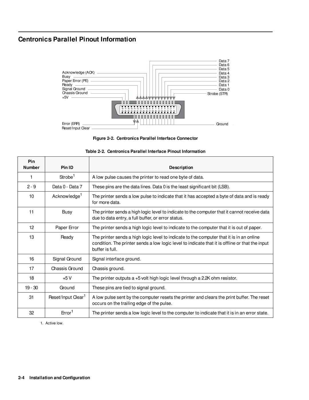
| Figure |
|
| Table | |
|
|
|
|
Pin |
|
|
|
Number | Pin ID |
| Description |
|
|
|
|
1 | Strobe1 |
| A low pulse causes the printer to read one byte of data. |
2 - 9 | Data 0 - Data 7 |
| These pins are the data lines. Data 0 is the least significant bit (LSB). |
|
|
|
|
10 | Acknowledge1 |
| The printer sends a low pulse to indicate that it has accepted a byte of data and is ready |
|
|
| for more data. |
|
|
|
|
11 | Busy |
| The printer sends a high logic level to indicate to the computer that it cannot receive data |
|
|
| due to data entry, a full buffer, or error status. |
|
|
|
|
12 | Paper Error |
| The printer sends a high logic level to indicate to the computer that it is out of paper. |
|
|
|
|
13 | Ready |
| The printer sends a high logic level to indicate to the computer that it is in an online |
|
|
| condition. The printer sends a low logic level to indicate that it is offline or that the input |
|
|
| buffer is full. |
|
|
|
|
16 | Signal Ground |
| Signal interface ground. |
|
|
|
|
17 | Chassis Ground |
| Chassis ground. |
|
|
|
|
18 | +5 V |
| The printer outputs a +5 volt high logic level through a 2.2K ohm resistor. |
|
|
|
|
19 - 30 | Ground |
| These pins are tied to signal ground. |
|
|
|
|
31 | Reset/Input Clear1 |
| A low pulse sent by the computer resets the printer and clears the print buffer. The reset |
|
|
| occurs on the trailing edge of the pulse. |
|
|
|
|
32 | Error1 |
| The printer sends a low logic level to the computer to indicate that it is in an error state. |
1. | Active low. |
|
|