Maintenance and Service Guide
HP Compaq Business PC Maintenance and Guide
About This Book
Iii
Iv About This Book
Table of contents
Page
Standard Configuration Features Serial Number Location
Smart ATA Drives Cable Management Hard Drive Capacities
Removal and Replacement Procedures Microtower MT Chassis 128
Page
Appendix C Post Error Messages 250
Accessing DPS Through Computer Setup 312
CMT Specifications 327 328 SFF Specifications 330
Contacting Customer Support 306
Usdt Specifications 331
Xii
Installing and Customizing the Software
Installing the Windows Operating System
Downloading Microsoft Windows Updates
Installing or Upgrading Device Drivers Windows systems
Customizing the Monitor Display Windows systems
Accessing Disk Image ISO Files
Launching Windows XP from Windows
Computer Setup F10 Utility
Computer Setup F10 Utilities
Using Computer Setup F10 Utilities
Computer Setup F10 Utilities
Computer Setup-File
Computer Setup F10 Utility
2Computer Setup-File
Computer Setup-Storage
3Computer Setup-Storage
Exit
OptionDescription
Configuration
Sata Defaults
Device
Removable Media Boot
Storage Options
Sata Emulation
Max eSATA Speed some models
Computer Setup-Security
4Computer Setup-Security
Boot Order
Shortcut to Temporarily Override Boot Order
Power-On
Password
Password Options
Smart Cover some
Network Boot
USB Security
Slot Security
System IDs
Computer Setup F10 Utilities
Computer Setup-Power
5Computer Setup-Power
Computer Setup-Advanced
6Computer Setup-Advanced for advanced users
Option Heading Power-On Options
Bios Power-On
VGA Configuration
AMT Configuration
Bus Options
Device Options
Recovering the Configuration Settings
Convertible minitower CMT chassis spare parts
Computer system components
Illustrated parts catalog
Cables
Convertible minitower CMT chassis spare parts
Description Spare part number
Misc parts
Drives
Item Description Spare part number
Description Spare part number Hard drive
Optical drive
Misc boards
Sequential part number listing
Convertible minitower CMT chassis spare parts
Illustrated parts catalog
Convertible minitower CMT chassis spare parts
Illustrated parts catalog
Convertible minitower CMT chassis spare parts
Illustrated parts catalog
Microtower MT chassis spare parts
Computer major components
Description Spare part number Front bezel
Cables
Misc parts
397117-001
Misc boards
Sequential part number listing
Microtower MT chassis spare parts
Illustrated parts catalog
Microtower MT chassis spare parts
Illustrated parts catalog
Microtower MT chassis spare parts
Description Spare part number Access panel
Ultra-Slim Desktop Usdt chassis spare parts
AC adapter
Cables
Misc parts
Chassis fan, front
Wlan Antenna Hardware Kit
Stand
Description Spare part number Optical drive
Ultra-Slim Desktop Usdt chassis spare parts
Illustrated parts catalog
Ultra-Slim Desktop Usdt chassis spare parts
Illustrated parts catalog
Ultra-Slim Desktop Usdt chassis spare parts
Small Form Factor SFF chassis spare parts
Cables
Misc parts
Description Spare part number Solenoid lock
GB Solid-state drive 646809-001 607817-001
Sequential part number listing
Illustrated parts catalog
Small Form Factor SFF chassis spare parts
Illustrated parts catalog
Small Form Factor SFF chassis spare parts
Illustrated parts catalog
Page
Electrostatic Discharge Information
Generating Static
Preventing Electrostatic Damage to Equipment
Relative Humidity Event 55% 40% 10%
Personal Grounding Methods and Equipment
Grounding the Work Area
Static Shielding Protection Levels
Method Voltage
Operating Guidelines
Recommended Materials and Equipment
General Cleaning Safety Precautions
Cleaning the Computer Case
Routine Care
Service Considerations
Cleaning the Keyboard
Cleaning the Monitor
Cleaning the Mouse
Power Supply Fan
Cables and Connectors
Tools and Software Requirements
Screws
Lithium Coin Cell Battery
Hard Drives
Sata Hard Drives
Sata Hard Drive Cables
Smart ATA Drives
Cable Management
Hard Drive Capacities
Configurations and Serial Number
Standard Configuration Features
2Microtower Configuration
4Ultra-Slim Desktop Configuration
Serial Number Location
6Microtower Serial Number and Product ID Location
Page
Preparation for Disassembly
Computer Access Panel
Description Spare part number Access panel 646819-001
Front Bezel
Description Spare part number Front bezel 646822-001
4Installing the Front Bezel Security Screw
Front Bezel Security
Bezel Blanks
System Board Connector System Board Label Color Component
System Board Connections
1System Board Connections
Memory
DIMMs
DDR3-SDRAM DIMMs
Populating Dimm Sockets
Installing DIMMs
Page
Expansion Card
9Removing an Expansion Slot Cover Expansion Card
Page
Page
Drives
Drive Positions
2Drive Positions
Removing a Drive from a Drive Bay
Page
Page
Installing Drives
Media
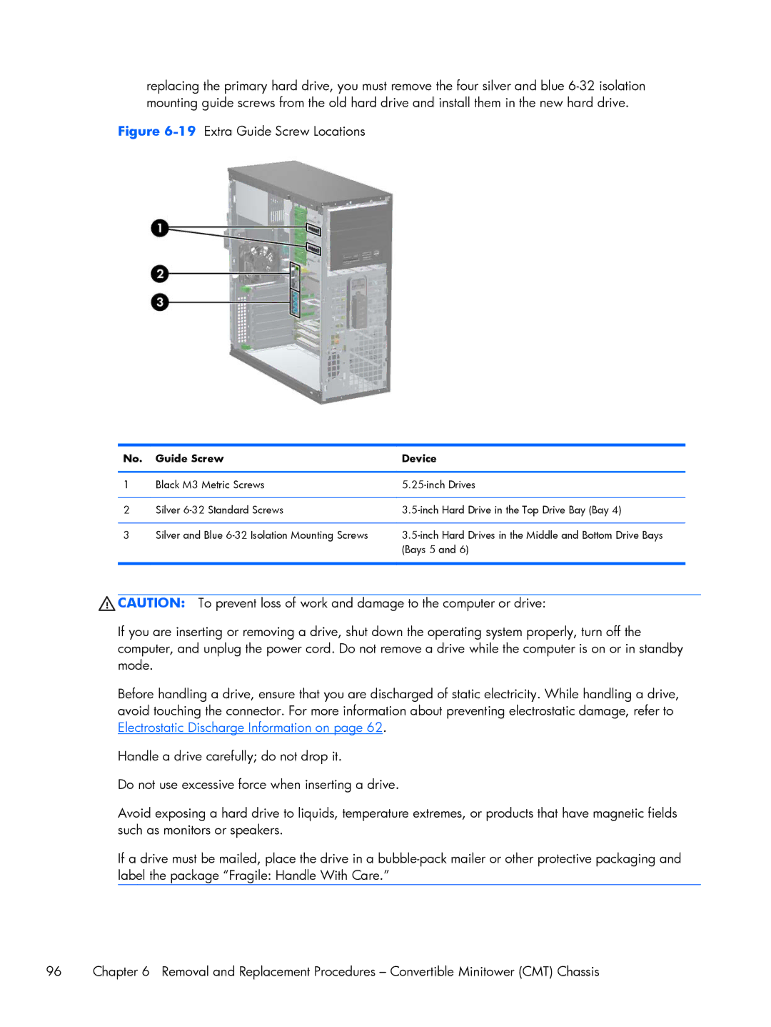
19Extra Guide Screw Locations
Guide Screw Device
Installing a 5.25-inch Drive into a Drive Bay
Page
Installing a Hard Drive into an Internal Drive Bay
Page
27Installing a Hard Drive into the Lower Two Bays Drives
Page
Page
Removing and Replacing a Removable 3.5-inch Sata Hard Drive
32Removing the Thermal Sensor Drives
Page
Page
Page
Hood Sensor
Description Spare part number Hood sensor 638816-001
Front I/O, USB Assembly
Page
Power Switch Assembly
Speaker
Description Spare part number Speaker 645330-001
Rear Chassis Fan
Description Spare part number Rear chassis fan 643908-001
Fan sink
Description Spare part number Fan sink 643907-001
Page
Processor
Description Spare part number Intel Core i7 processor
Intel Core i5 processors
Intel Core i3 processors
Page
Secure the locking lever
Power Supply
System Board
Page
Changing from a Minitower to a Desktop Configuration
Page
Changing from a Desktop to a Minitower Configuration
Page
Page
Removal and Replacement Procedures Microtower MT Chassis
1Removing the Computer Access Panel
Description Spare part number Access panel 646825-001
Remove the access panel Computer Access Panel on
Description Spare part number Front bezel 646826-001
3Removing a Bezel Blank Bezel Blanks
48200 Elite Series System Board Connections
18200 Elite Series System Board Connections
56200 Pro Series System Board Connections
26200 Pro Series System Board Connections
134 Removal and Replacement Procedures Microtower MT Chassis
Populating Dimm Sockets
136 Removal and Replacement Procedures Microtower MT Chassis
Page
Expansion Cards
8Removing an Expansion Slot Cover Expansion Cards
Page
Page
Drive Positions
3Drive Positions
Drives
14Extra Guide Screw Locations
Removing a 5.25-inch or 3.5-inch Drive from a Drive Bay
Page
Installing a 5.25-inch or 3.5-inch Drive into a Drive Bay
18Sliding the Drives into the Drive Cage
Page
Installing a Hard Drive into an Internal Drive Bay
Removing a Hard Drive from a Drive Bay
Page
24Securing the Drive in the Adapter Bracket Drives
Page
Front Fan Assembly
Description Spare part number Front fan assembly 585884-001
Page
Front I/O Assembly
Description Spare part number Front I/O assembly 646827-001
Power Switch/LED Assembly
Heat sink
Description Spare part number Heat sink 645326-001
Page
Processor
Page
Page
Speaker
Description Spare part number Rear chassis fan 636922-001
Page
Power Supply
Page
For use in 6200 Pro Series models
Page
Preparation for Disassembly
Access Panel
Description Spare part number Access panel 646815-001
Description Spare part number Front bezel 646814-001
3Removing a bezel blank Replace the front bezel
DDR3-SDRAM DIMMs
Installing DIMMs
Page
Expansion Card
6Removing an expansion slot cover Expansion Card
Page
Page
White 1st Optical Drive
126200 Pro Series system board connections
Drives
Drive Positions
Installing and Removing Drives
Removing a 5.25-inch Drive from a Drive Bay
15Removing the 5.25-inch Drive
Removing a 3.5-inch Drive from a Drive Bay
Installing a 3.5-inch Drive into a Drive Bay
Page
Page
24Removing the Hard Drive Drives
Page
Fan duct
Description Spare part number Fan duct 636921-001
Description Spare part number Front fan 645327-001
Page
Hood Sensor
Front I/O, Power Switch Assembly
Remove the chassis fan Front Fan Assembly on
Page
Description Spare part number Speaker 636925-001
34Loosening the heat sink screws 200
Page
Description Spare part number Intel Core i7 processors
Page
Page
Power Supply
Page
System Board
Page
Using the Small Form Factor Computer in a Tower Orientation
Preparation for Disassembly
Description Spare part number Access panel 646816-001
Description Spare part number Front bezel 646817-001
Bezel Blank
3Removing a bezel blank Bezel Blank
4System board connections
SODIMMs
DDR3-SDRAM SODIMMs
Populating Sodimm Sockets
1SODIMM socket locations
Description System Board Label Socket Color
Installing SODIMMs
6Removing a Sodimm Memory
Page
Front Fan
Description Spare part number Front fan 646813-001
Optical Drive
Removing the Optical Drive
Preparing the New Optical Drive
10Aligning the release latch Optical Drive
Installing the New Optical Drive
Hard Drive
12Unlocking the hard drive carrier Hard Drive
Page
Page
Page
Optical Drive Rail
Card Reader
Description Spare part number Card reader 593235-001
Page
Description Spare part number Speaker 647447-001
Description Spare part number Heat sink 587456-001
Page
2600S, 2.8 GHz, 8-MB L3 cache, 95W 638419-001
Page
Secure the locking lever
TV Tuner or Wlan Module
Hood Sensor
System Board
Page
Rear Fan
Description Spare part number Rear fan 605155-001
Page
Changing from Desktop to Tower Configuration
Port Cover
Description Spare part number Port cover 646818-001
Power Supply, External
36Removing a port cover
Battery Replacement
Lift the battery out of its holder
Figure A-2Removing and Replacing a Coin Cell Battery Type
Page
Japanese Power Cord Requirements
General Requirements
Country-Specific Requirements
Country-Specific Requirements 249
Country Accrediting Agency
Post Error Messages
Post Numeric Codes and Text Messages
Post Numeric Codes and Text Messages
Table C-1Numeric Codes and Text Messages
Control panel message Description Recommended action
Control panel message Description
Verify monitor is attached and turned
Reseat CPU or chassis fan
Under Storage DPS Self-test
Change Storage Storage Options
Sata Emulation to IDE, and select File
Save Changes and Exit. Reenter
Appendix C Post Error Messages
If the error persists, update to the latest
Bios version and ME firmware version
Table C-2Diagnostic Front Panel LEDs and Audible Codes
Activity Beeps Possible Cause Recommended Action
Activity Beeps Possible Cause
Once a bad card is identified, remove
Troubleshooting Without Diagnostics
Safety and Comfort Before You Call for Technical Support
Helpful Hints
Refer to Helpful Hints on page 264 in this guide
Page
Solving General Problems
266 Appendix D Troubleshooting Without Diagnostics
Table D-1Solving General Problems
There is no sound or sound volume is too low Cause Solution
Cannot remove computer cover or access panel Cause Solution
Poor performance is experienced Cause Solution
268 Appendix D Troubleshooting Without Diagnostics
Run Windows XP or Start All Programs
Solving General Problems
Solving Power Problems
270 Appendix D Troubleshooting Without Diagnostics
Table D-2Solving Power Problems
Power supply shuts down intermittently Cause Solution
Voltage. Proper voltage setting depends on your region
Solving Diskette Problems
272 Appendix D Troubleshooting Without Diagnostics
Table D-3Solving Diskette Problems
Cannot format diskette Cause Solution
Problem has occurred with a disk transaction Cause Solution
Diskette drive cannot read a diskette Cause Solution
Storage Storage Options
274 Appendix D Troubleshooting Without Diagnostics
Solving Hard Drive Problems
Table D-4Solving Hard Drive Problems
276 Appendix D Troubleshooting Without Diagnostics
Storage Boot Order list
Computer will not boot from hard drive Cause Solution
Device Configuration
Computer seems to be locked up Cause Solution
Solving Media Card Reader Problems
278 Appendix D Troubleshooting Without Diagnostics
Table D-5Solving Media Card Reader Problems
Can not write to the media card Cause Solution
Solving Media Card Reader Problems 279
Solving Display Problems
280 Appendix D Troubleshooting Without Diagnostics
Table D-6Solving Display Problems
Blank screen no video Cause Solution
Dim characters Cause Solution
282 Appendix D Troubleshooting Without Diagnostics
Image is not centered Cause Solution
Out of Range displays on screen Cause Solution
Select ImageControl/ Horizontal Position or Vertical
Certain typed symbols do not appear correct Cause Solution
Symbol. Click Start All Programs Accessories
System Tools Character Map. You can copy
Solving Audio Problems
284 Appendix D Troubleshooting Without Diagnostics
Table D-7Solving Audio Problems
Line-in jack is not functioning properly Cause Solution
Advanced Device Options Internal Speaker
Solving Printer Problems
286 Appendix D Troubleshooting Without Diagnostics
Table D-8Solving Printer Problems
Printer will not turn on Cause Solution
Printer prints garbled information Cause Solution
Printer is offline Cause Solution
Solving Keyboard and Mouse Problems
288 Appendix D Troubleshooting Without Diagnostics
Table D-9Solving Keyboard Problems
Down
Solving Keyboard and Mouse Problems 289
Table D-10Solving Mouse Problems
Solving Hardware Installation Problems
290 Appendix D Troubleshooting Without Diagnostics
Table D-11Solving Hardware Installation Problems
Solving Hardware Installation Problems 291
Computer will not start Cause Solution
Solving Network Problems
292 Appendix D Troubleshooting Without Diagnostics
Table D-12Solving Network Problems
Wake-on-LAN feature is not functioning Cause Solution
Click Configure
Select Advanced Device Options S5 Wake on
Select Start Control Panel
Double-clickNetwork Connections
294 Appendix D Troubleshooting Without Diagnostics
Network status link light never flashes Cause Solution
Diagnostics reports a failure Cause Solution
New network card will not boot Cause Solution
Solving Memory Problems
296 Appendix D Troubleshooting Without Diagnostics
Table D-13Solving Memory Problems
Out of memory error Cause Solution
Solving Processor Problems
Table D-14Solving Processor Problems
Memory count during Post is wrong Cause Solution
Insufficient memory error during operation Cause Solution
Solving CD-ROM and DVD Problems
298 Appendix D Troubleshooting Without Diagnostics
Table D-15Solving CD-ROM and DVD Problems
Cause Solution
Movie will not play in the DVD drive Cause Solution
Cannot eject compact disc tray-load unit Cause Solution
On Options
Solving USB Flash Drive Problems
300 Appendix D Troubleshooting Without Diagnostics
Table D-16Solving USB Flash Drive Problems
Disconnect the drive cable from the system board
USB flash drive not found identified Cause Solution
System will not boot from USB flash drive Cause Solution
Ports under Security Device Security
Solving Front Panel Component Problems
Solving Internet Access Problems
302 Appendix D Troubleshooting Without Diagnostics
Table D-17Solving Front Panel Component Problems
Solving Internet Access Problems 303
304 Appendix D Troubleshooting Without Diagnostics
Solving Software Problems
Table D-19Solving Software Problems
Contacting Customer Support
Cmos
Resetting the Password Jumper
Clearing and Resetting the Cmos
Locate, press, and hold the Cmos button in for five seconds
Figure E-1 Cmos button
Drive Protection System DPS
Accessing DPS Through Computer Setup
Select Storage DPS Self-Test
Hewlett-Packard Vision Diagnostics
Accessing HP Vision Diagnostics
Survey Tab
Test Tab
Status Tab
Errors Tab
History Tab
Saving and Printing Information in HP Vision Diagnostics
Downloading the Latest Version of HP Vision Diagnostics
Help Tab
Protecting the Software
Click the Download button
Windows 7 Backup and Recovery
Backing up your information
Select Start All Programs Maintenance Backup and Restore
Performing a recovery
Using the Windows recovery tools
Using F11
Windows Vista Backup and Recovery
Follow the on-screen instructions Click Next
Follow the on-screen instructions
Performing a recovery
Using the Windows recovery tools
Under I need help immediately, tap System Recovery
CMT Specifications
CMT Specifications
Table I-1Specifications
MT Specifications
Appendix I Specifications
Table I-2Specifications
Standard Efficiency
MT Specifications
SFF Specifications
Table I-3Specifications
Rated Input Current
Usdt Specifications
Usdt Specifications
Table I-4Specifications
Backing up 307 Clearing and resetting 309
Index
SFF
184 SFF locations 183
Usdt spare part number
Usdt hard drive 223
215 Usdt optical drive
Spare part number Index
196 SFF power supply 205
MT speaker 162
202 SFF speaker 199 SFF system board 207
Usdt card reader 228 Usdt front bezel 212 Index
Power supply, spare part
Sata
238 Usdt spare part number System board connections 132