HP DesignJet 700 Plotter HP DesignJet 750C Plus Plotter
R N I N G U T I O N
HP DesignJet 700 Plotter HP DesignJet 750C Plus Plotter
Page
Finding Information
750C Plus
To find how to Go to
Where To Find the Most Commonly Needed Information
Contents
Working with Media and Cartridges
Vii
To Switch between Color and Monochrome
How Does Rotate Interact with Your Software?
Managing Your Plots
Quick Guide to Whether Recalibration Is Necessary
Reconfiguring the Plotter
Solving Problems with Plot Position or Content
Using the Documentation to Help Solve Problems
If a Sheet Is Ejected When You Switch On the Plotter
If There is a Problem Communicating between Your Computer
If An ªOut Of Memory/Data Was Lostº Message Is Displayed
If the Access Cartridges Key Does Not Work
Xii
To Obtain a Material Safety Data Sheet Msds
HP-GL/2 and HP RTL Programming Information
Xiii
Welcome
Media
Print Quality
Software Applications and Drivers
User Interface
Memory and Upgrades
Xvii
Front View
Xviii
Rear View
Setting Up Your Plotter
Fast Track
Fast Track
Done? �
Set Up Checklist
Set up your software Print a test plot
Set Up Checklist
For details of the memory expansion modules available, see
Task 1 Check That You Have All the Items Required
Roll of HP Coated Paper for the HP DesignJet 750C Plus
For details of suitable cables, see
Task 2 Optional Install Memory Expansion Modules
Task 2 Install Memory Expansion Modules Optional
Cover plate
Task 2 Optional Install Memory Expansion Module
R N I N G
If English not OK
To Load a Roll
Task 4 Load Media
End cap removed
Media path
1838
Sheet load ±±±±±±±± Roll load
If you are using the roll supplied with the plotter
0018
To Load a Sheet
Enter
Task 5 Load the Print Cartridges
Task 5 Load the Print Cartridges
U T I O N R N I N G
1754
U T I O N
Task 6 Optional Print a Demonstration Plot
Task 6 Print a Demonstration Plot Optional
On the front-panel display, go to Demos, as shown below
700
Task 7 Connect the Plotter to Your Computer
If You Are Connecting the Plotter Directly to a Network
Task 7 Connect the Plotter to Your Computer
If You Are Connecting the Plotter Directly to Your Computer
Serial RS-232-C Settings
Task 8 Configure the Interface Serial Interface Users
Task 8 Serial Interface Users Only Configure the Interface
To Change the Plotters Serial Interface Settings
Menu Mode
Get to the routine for defining a new serial configuration
Baudrate
Switch to the new configuration
Publishing system etc
Task 9 Set Up Your Software
Task 9 Set Up Your Software
Basic Terminology
Typical Checklist of Tasks to Set Up Your Software
For use Supplied Installation Or optional
Preference Device Comments
Other Applications
Task 10 Print a Test Plot
Task 10 Print a Test Plot
Extra Tips For Unix Users
Extra Tips for Unix Users
Which Interface?
Print Spooler Configuration Examples
Make sure the plotters baud rate is 9600 and parity is even
Select
Start the Administration Tool utility from OpenWindowst
Page
Learning How To Use the Front Panel Display
Front Panel
Front Panel
Keep the plot for later reference
Display Section
Menu title
Printing the Menus Plot
Printing the Menus Plot
Description of the Menus Plot
Or the Full Menus screen
Entering the Menu System
With a Status screen displayed, for instance
Press the Enter key Either the Short Menus screen
Navigating the Menu System
Navigating the Menu System
Palette= ³ Pen settings ³ Merge= ³ Define palette ³
Menu Graphics Used in this Manual
Other Types of Screen
Other Types of Screens
Or for changing the language
Press the Enter key
Examples
Example 1 Changing Margins
Enter the menu system by pressing the Enter key
Press the Enter key to display the Margins menu
Example 2 Changing the Drying Time
Press the Enter key to display the Drying Time menu
Page
Working With Media and Cartridges
Choosing Media
Choosing Media
Five Important Points about Media Types
Supported Media Types
Media Type on Physical Characteristics
Physical Characteristics of Media Types
Front-panel Display Each Other
Cost and Color Support of Media Types
Media Type on Cost Relative to
Fast Normal Best
Combinations of Media Type and Print Quality
Typical Media Type Choices by Application
Packages
CAD1 and GIS1
Imaging and graphics
Caring For Your Media
Caring For Your Media
Loading Media
Loading Media
To Change a Roll
Lower the media lever
1837a
Endcap removed
Media should wind up from behind the roll
R N I N G
Sheet load ±±±±±±±± Roll load
For advice on media types, see
1840
Media Type Media-Loading Tips
Sheet load ±±±±±±±± Roll load
For advice on media types, see
Compensating for Badly Cut Media
To Adjust Skew Tolerance
Typical Drying Times minutes
Unloading Media
Drying Time
Unloading Media
Drying Time Selected Result Front Panel
To Adjust Drying Time
To Unload a Sheet After Plotting
Either
To Remove an Unused Sheet
To check a cartridges ink level
When to Replace Cartridges
Replacing Cartridges
Replace the cartridges in the following three circumstances
Before Replacing Cartridges
To Replace a Cartridge
Black Yellow Cyan Magenta
Cartridges label with the color of the dot above the stall
For the HP DesignJet 750C Plus, match the color
Controlling the Page Format
Standard media sizes, see
Relative dimensions
Size
Explained on
Do You Need to Adjust the Page Size in the Front Panel?
Size Comments Front Panel
To Adjust the Page Size from the Front Panel
Size and Nesting Roll Media Only
Size and Clipped Plots
Smaller Margins
Adjusting the Margins Roll Media Only
Adjusting the Margins Roll Media Only
Margins and Automatic Cutting
Rotating a Plot
Rotating a Plot
Rotating a Drawing from the Front Panel
To Rotate a Plot from the Front Panel
Rotate Feature and Clipped Plots
Exactly What Is Rotated?
How Does Rotate Interact with Your Software?
Plotting a Mirror Image
Plotting a Mirror Image
Controlling a Plots Overall Appearance
Ways To Control the Plots Appearance
Ways to Control the Plots Appearance
Palette Plot, as explained on
To See the Current Palette Settings
HP DesignJet 700 any of the plotters 11 pen shades
Through
255,0,255
To See the Colors Available for a Palette
Available Options
To Change the Palette Settings
Palette Comments
To Change the Selection of the Current Palette
Changing the Treatment of Overlapping Lines Merge Feature
Changing the Treatment of Overlapping Lines Merge Feature
Changing the Overall Lightness/Darkness of a Plot
Changing the Overall Lightness/Darkness of a Plot
Printing Color Drawings in Monochrome
Printing Color Drawings in Monochrome
To Switch between Color and Monochrome
Choosing an Appropriate Print Quality
Affects next plot sent Choosing an Appropriate Print Quality
Color
300 x
Normal 600 x 600
Best 600 x 600
Affects next plot sent. To Change the Print Quality
Improving Line Quality and Graphics Detail
���������
Page
Managing Your Plots
To Cut a Plot Before Drying Is Complete Roll Media Only
To Cancel a Plot
Managing Plots Currently Being Printed or Drying
To resume printing, press Pause again
To Pause while Printing a Series of Plots
Managing Plots Not Yet Printed The Queue
To Start Printing a Plot That is Waiting for a Timeout
Managing Plots Not Yet Printed The Queue
What is the Queue?
To Identify a Page in the Queue
Statistic Comments
To See the Size of a Page in the Queue
To Prioritize a Page in the Queue
To Delete a Page from the Queue
To Make Copies of a Page in the Queue
Replot an Image Using the Plotters Memory
Replot an Image Using the Plotters Memory
Avoiding Media Waste by Nesting Pages Roll Media Only
What is Nesting?
Avoiding Media Waste by Nesting Pages Roll Media Only
Either all are 300 dpi or all are 600 dpi ± see
When Does the Plotter Try to Nest Pages?
Which Pages Qualify for Nesting?
Which Pages May be Rotated?
How Long Does the Plotter Wait for Another File?
Nest Setting Plotters Response Selected
To Turn Nesting On or Off and Choose the Nesting Method
What Happens to Nesting if you Turn Queueing Off?
Getting the Best from Nesting Nesting and Margins
Nesting and the Rotate Feature
Page
Reconfiguring Your Plotter
To See the Current Overall Configuration of the Plotter
To See the Current Overall Configuration of the Plotter
To See the Current Configuration of the Front-Panel Settings
To Change the Front-Panel Settings
To Change the Front-Panel Settings
Recalibrating the Plotter for Accuracy
When to Recalibrate the Plotter
Recalibrating the Plotter for Accuracy
Quick Guide to Whether Recalibration is Necessary
To Recalibrate the Plotter
To Restore the Factorys Calibration
From the Accuracy menu, choose Restore factory. Thats all
Graphics Comments Language
To Change the Graphics Language Setting
Graphics Language and Networks
Changing the Interface Settings and I/O Timeout Setting
Changing the Interface Settings
To Change the I/O Timeout Setting
To Change the Serial Interface Settings
File Size and Memory Usage
To Upgrade Your Plotter with More Memory
To Upgrade Your Plotter with More Memory
To Upgrade Your Plotter with the Postscript Option
To Upgrade Your Plotter with the Postscript Option
HP JetDirect Print Server
To Upgrade Your Plotter with a Network Interface
To Upgrade Your Plotter with a Network Interface
Maintaining Your Plotter
Replacing the Print Cartridges
Cleaning the Plotter
Replacing the Print Cartridges and Cleaning the Plotter
ªNormalº Plotter Use
ªNormalº Plotter Use
To Print the Service Configuration Plot
Troubleshooting
Using the Documentation to Help Solve Problems
Using the Documentation to Help Solve Problems
Locating the Source of Problem
Locating the Source of the Problem
Roll media
Solving Media-Handling Problems
Solving Media-Handling Problems
Have you
If Plots Do Not Feed Out Properly From the Plotter
If Media Crumples When You Load it
If Plots Do Not Stack Properly in the Bin
If a Sheet Is Ejected When You Switch On the Plotter
If the Automatic Cutter Does Not Work
If Plots Fall on the Floor After Being Cut
Solving Print-Cartridge Problems
Solving Print-Cartridge Problems
If Brand New Cartridges Have Problems
Clearing a Media Jam
Clearing a Media Jam
Solving Communication Problems
Solving Communication Problems
If the Plot Is Completely Blank
Solving Problems with Plot Position or Content
Solving Problems with Plot Position or Content
If the Output Contains Only a Partial Plot
If a Long-Axis Plot Is Clipped
If the Plot Is Clipped
If the Plot Is Inaccurate
Check the front-panel Page format / Mirror setting
If the Plot Is Unexpectedly Rotated
If the Plot Is a Mirror Image of Your Drawing
If One Plot Overlays Another Plot on the Same Sheet
If Pen Settings Seem To Have No Effect
If the Plot Is Distorted or Unintelligible
Trouble Shooting
If There Are White Streaks in Solid Fill Areas
Solving Print-Quality Problems
Solving Print-Quality Problems
If the Color Is Not as Expected
If There are Other Gaps in Solid Areas or in Lines
If One or More Cartridges are not Printing at All
If There are Jagged Vertical or Horizontal Lines
If There are Slightly Warped Lines
If There are Color ªShadowsº
If the Plot Is Too Dark or the Color Too Saturated
If There are Blurred Lines Ink ªBleedsº from Lines
If There are Blotchy Areas Uneven Fill Density
If Ink Smears After You Remove a Plot
If There Is Pronounced Banding in Area Fills
If None of the Front-Panel Keys Work
Solving Front-Panel Problems
If the Access Cartridges Key Does Not Work
Solving Front-Panel Problems
If an ªOut Of Memory/Data Was Lostº Message Is Displayed
If a ªSystem Errorº Message Is Displayed
If the Plotter Seems Too Slow
Solving Miscellaneous Problems
Correctly and that there is power available at the socket
If the Plotter Does not Plot
If the Bail Black Metal Bar Does Not Lower All the Way
Change the Nest wait setting. See
If the Plotter Waits Too Long to Plot a Nest
Getting Help
Getting Help
What to Do Before You Call
If a Repair Is Needed
Page
10-1
Front-Panel Messages
Message Explanation and Action
Front-Panel Messages
Messages are listed in alphabetical order
10-2
Continue
10-3
Reload
10-4
Plotter
10-5
10-6
11-1
Reference
11-2
Plotter Specifications
Plotter Specifications
Functional Specifications
11-3
Plotter Specifications Functional Specifications
11-4
Plotter Specifications Environmental Specifications
Power Specifications
Acoustic Specifications
11-5
Safety Specifications
Media
11-6
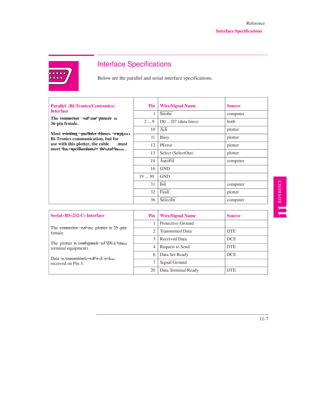
Serial RS-232-C Interface Pin Wire/Signal Name Source
Interface Specifications
Below are the parallel and serial interface specifications
Interface Specifications
Cables for PCs
Interface Cables
11-8
Interface Cables
Cables for Unix systems
11-9
Dept. MSDS, Cupertino, CA 95014, U.S.A
To Obtain a Material Safety Data Sheet Msds
Regulatory Notices
Electromagnetic Compatibility EMC
LpA 70 dB am Arbeitsplatz im Normalbetrieb nach DIN 45635 T
Telecommunications Statement
IEC 950 1991 + A1, A2 / EN 60950 1992 + A1, A2
InkJet Plotter
HP C4705A, HP C4706A, C4708A, C4709A
HP JetDirect network interface card
11-13
Ordering Accessories
Users Guide and Quick Reference Guide Chinese C4705-60030
Media Supplies
11-14
Drivers
HP Part Number
11-15
Ordering Accessories HP Part Number Network Interface
Spindle Assembly
A0-size C3173A A1-size C3172A
Is 800 538 11-16
How to Order Supplies and Accessories
HP-GL/2 and HP RTL Programming Information
12-1
Glossary
Glossary
12±3
Glossary
Index
Index
Options
Index
USA
Manual Part Number C4705-90031 Edition 1, September English
Customer re-order number C4705-60021