Maintenance and Troubleshooting
FC interface controller problems
Most problems occur during the initial installation of the interface controller. Before proceeding with advanced troubleshooting techniques, verify all connections and review the configuration.
LED indicators
The LED indicators on the
■SCSI bus LEDs
■FC port LEDs — indicate FC activity (ACT) and link (LNK) status. If the link LED does not light it may indicate a problem with a FC link. Verify the FC port configuration and cabling.
■Ethernet LEDs — indicate activity and link status. If one of these indicators does not light or stays continuously lit, it may indicate a problem with the network connection or cabling. Verify the network connection. The port must be connected to a 10/100BaseT Ethernet network to function properly.
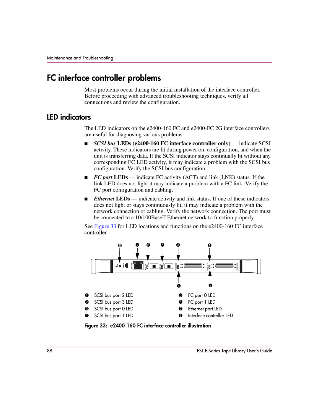
See Figure 33 for LED locations and functions on the
8 | 7 |
| 6 | 5 | 3 | 1 | |||||
|
|
|
|
|
|
|
|
|
|
|
|
|
|
|
|
|
|
|
|
|
|
|
|
|
|
|
|
|
|
|
|
|
|
|
|
|
|
|
|
|
|
|
|
|
|
|
|
|
|
|
|
|
|
|
|
|
|
|
|
|
|
|
|
|
|
|
|
|
|
|
|
|
| 4 | 2 |
1 | SCSI bus port 2 LED | 5 | FC port 0 LED |
2 | SCSI bus port 3 LED | 6 | FC port 1 LED |
3 | SCSI bus port 0 LED | 7 | Ethernet port LED |
4 | SCSI bus port 1 LED | 8 | Interface controller LED |
Figure 33: e2400-160 FC interface controller illustration
88 | ESL |
