2. Unit Description
2.1. Front Panel Components
|
| www.wti.com |
|
| ||
| PWR | SET | STATUS |
| ACTIVITY | Console Management Switch + Power Control |
| CLEAR | RDY DCD | 1 | 2 3 4 5 | 6 | |
| ON |
| ||||
1 | 2 | 3 | 4 | 5 | 6 |
|
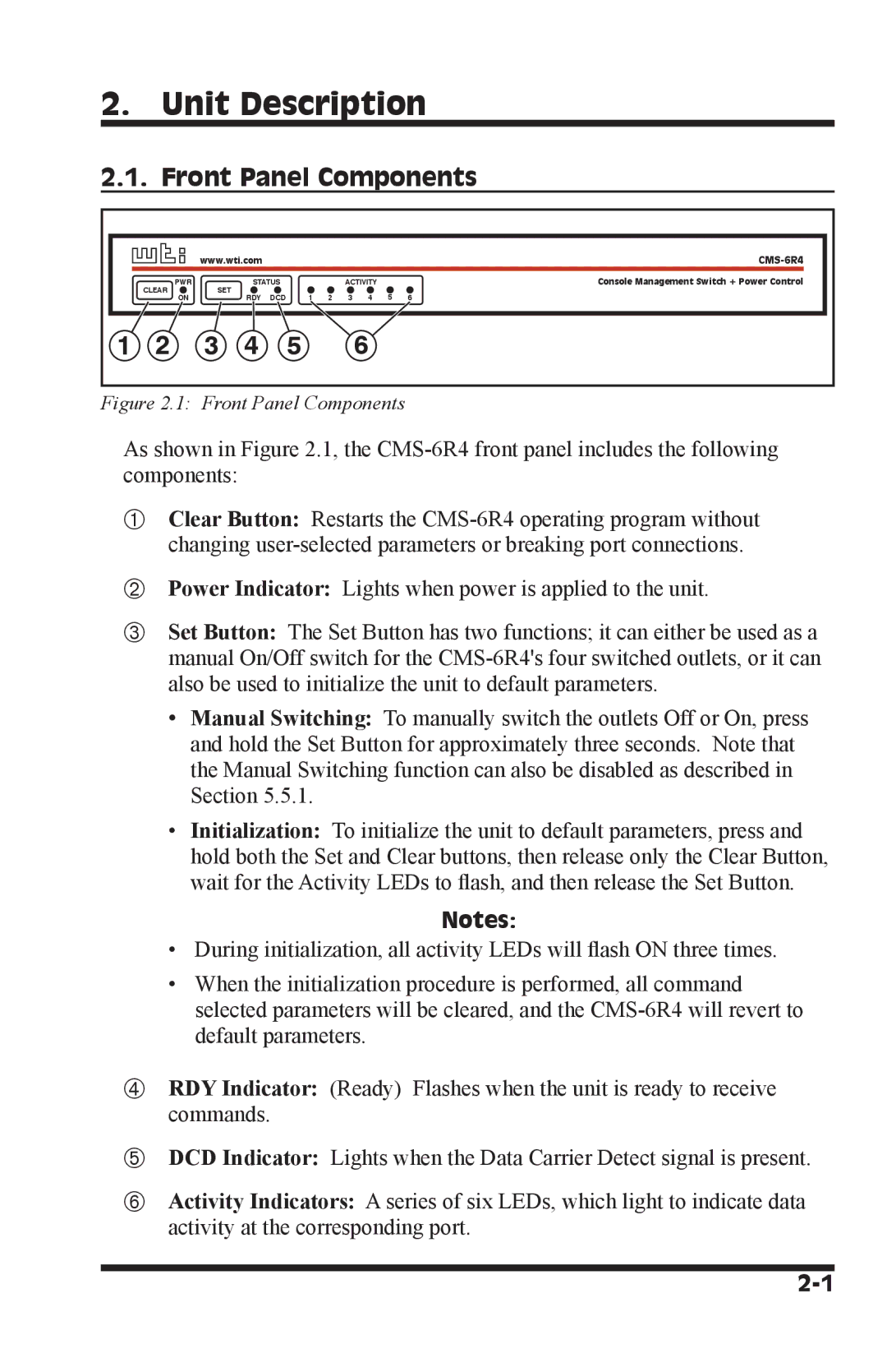
Figure 2.1: Front Panel Components
As shown in Figure 2.1, the
Clear Button: Restarts the
Power Indicator: Lights when power is applied to the unit.
Set Button: The Set Button has two functions; it can either be used as a manual On/Off switch for the
•Manual Switching: To manually switch the outlets Off or On, press and hold the Set Button for approximately three seconds. Note that the Manual Switching function can also be disabled as described in Section 5.5.1.
•Initialization: To initialize the unit to default parameters, press and hold both the Set and Clear buttons, then release only the Clear Button, wait for the Activity LEDs to flash, and then release the Set Button.
Notes:
•During initialization, all activity LEDs will flash ON three times.
•When the initialization procedure is performed, all command selected parameters will be cleared, and the
RDY Indicator: (Ready) Flashes when the unit is ready to receive commands.
DCD Indicator: Lights when the Data Carrier Detect signal is present.
Activity Indicators: A series of six LEDs, which light to indicate data activity at the corresponding port.