CMS-6R4 Series - User’s Guide
6
15 AMPS | PLUG 1 | PLUG 2 | PLUG 3 | PLUG 4 |
MAX |
|
|
|
|
|
| O | I |
5 | 3 | SYSTEM | 1 |
|
|
|
|
SETUP |
|
|
|
| |||
|
| PORTS |
|
|
|
|
|
6 | 4 |
| 2 | ACT | 10BaseT | PHONE LINE | |
1 | 2 | 3 | 4 | 5 |
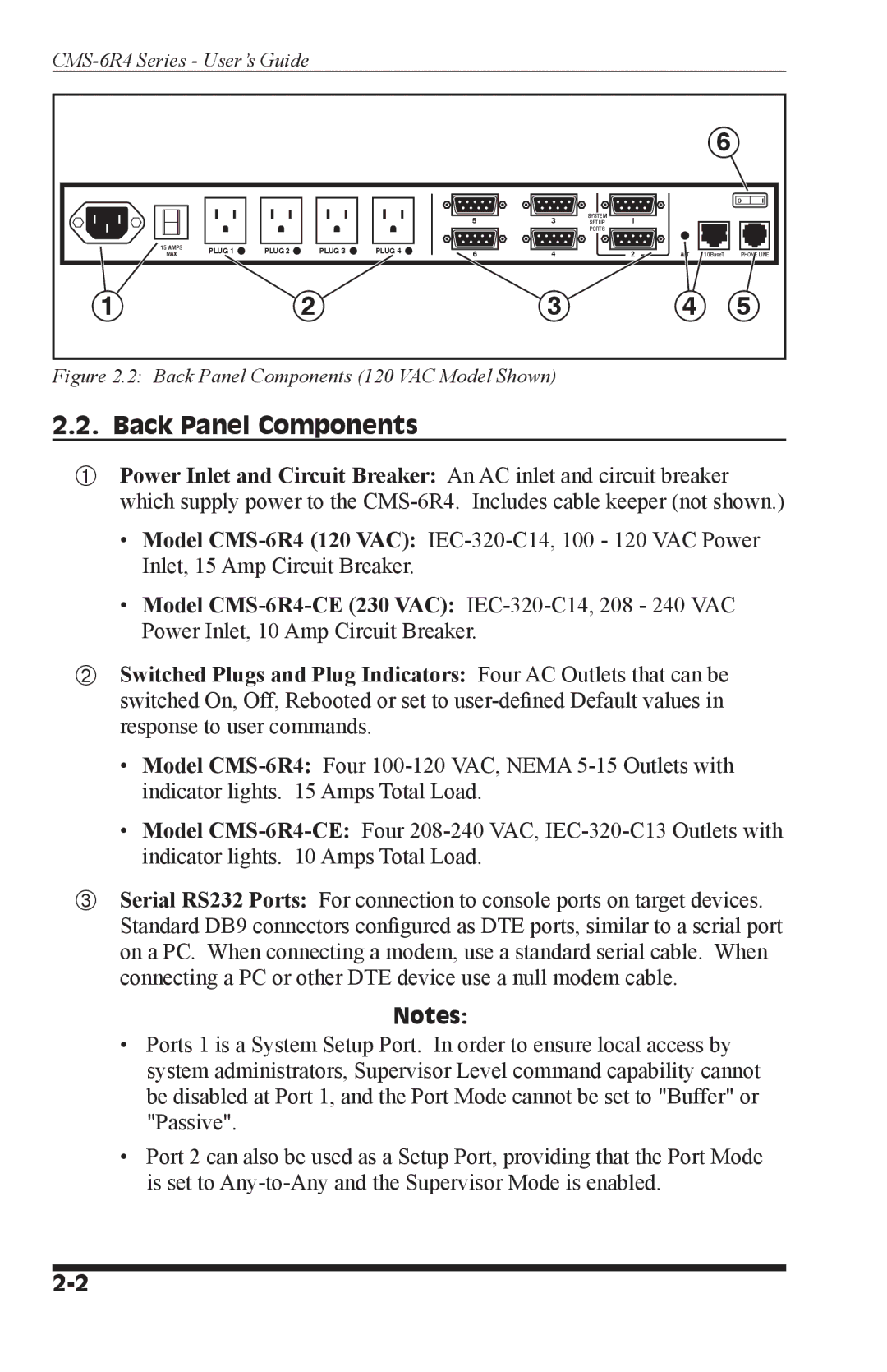
Figure 2.2: Back Panel Components (120 VAC Model Shown)
2.2. Back Panel Components
Power Inlet and Circuit Breaker: An AC inlet and circuit breaker which supply power to the
•Model
•Model
Switched Plugs and Plug Indicators: Four AC Outlets that can be switched On, Off, Rebooted or set to
•Model
•Model
Serial RS232 Ports: For connection to console ports on target devices. Standard DB9 connectors configured as DTE ports, similar to a serial port on a PC. When connecting a modem, use a standard serial cable. When connecting a PC or other DTE device use a null modem cable.
Notes:
•Ports 1 is a System Setup Port. In order to ensure local access by system administrators, Supervisor Level command capability cannot be disabled at Port 1, and the Port Mode cannot be set to "Buffer" or "Passive".
•Port 2 can also be used as a Setup Port, providing that the Port Mode is set to