IBM
Page
Contents
Index
Safety
Vi IBM xSeries 220 User’s Reference
Vii
Viii IBM xSeries 220 User’s Reference
Statement
IBM xSeries 220 User’s Reference
Introducing the IBM xSeries
Features and specifications
What your xSeries 220 offers
Reliability, availability, and serviceability features
Server controls and indicators
Cover-release latch Key lock
Turning on the server
Turning off the server
Air circulation
Comfort
Glare and lighting
Electrical outlets and cable lengths
Using the Configuration/Setup Utility program
Starting the Configuration/Setup Utility program
System Information
Choices available from the Configuration/Setup main menu
System Summary
Product Data
Power-on Password
Administrator Password
Devices and I/O Ports
Memory Settings
Advanced Setup
Processor Serial Number Access
System Partition Visibility
Using passwords
Power-on password
Administrator password
Starting the SCSISelect Utility program
Using the SCSISelect Utility program
Type of password Results
Choices available from the SCSISelect menu
Choices available from the PXE Boot Agent menu
Using the PXE Boot Agent Utility program
Starting the PXE Boot Agent Utility program
Setup time wait menu
Legacy OS wake up support
Using the ServerGuide CDs
Features at a glance
Setup and configuration overview
Setup and Installation CD
Typical NOS installation
System Partition
Setting up or updating multiple servers
Installing your NOS without ServerGuide
Error symptoms
Additional programs included with ServerGuide
IBM xSeries 220 User’s Reference
Installing options
Major components of the xSeries 220 server
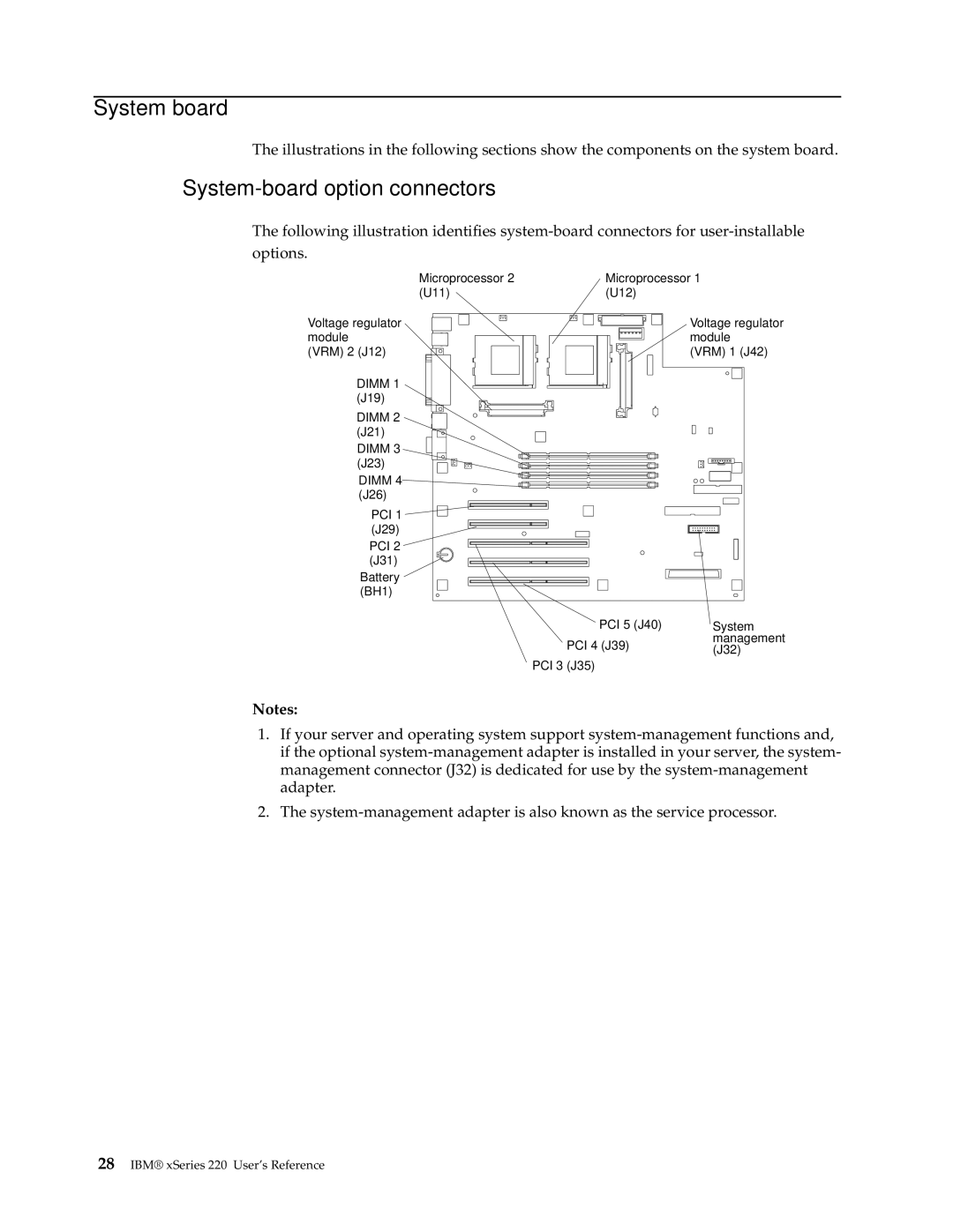
System-board option connectors
System board
System-board internal cable connectors
System-board external port connectors
Switch Number Description
System-board jumpers and switches
System-board switch block
System-board jumper blocks
Handling static-sensitive devices
Before you begin
System reliability considerations
Safety information
Installing options
IBM xSeries 220 User’s Reference
Installing options
Statement
Rotating the stabilizing feet
Removing the side cover
Removing the support bracket assembly
Working with adapters
Adapter considerations
Installing an adapter
IBM xSeries 220 User’s Reference
Scsi cable ServeRAID adapter Scsi connector J41
Installing internal drives
Internal drive bays
Preinstallation steps all bays
Installing a drive in bay 1, 2, 3, or
Installing options
Installing a non-hot-swap hard disk drive in bay 5, 6, or
Installing a hot-swap hard disk drive in bay 5, 6, or
IBM xSeries 220 User’s Reference
Installing memory modules
Dimm
Installing options
Installing and removing a microprocessor
Installing a microprocessor
Installing options
IBM xSeries 220 User’s Reference
VRM
Removing a microprocessor
Installing options
Installing the side cover
Connector locations
Connecting external options
Installation procedure
Viewing or changing the port assignments
Input/output ports
Parallel port
Serial ports
Parallel port connector
Pin SPP/ECP Signal EPP Signal
Universal Serial Bus ports
Serial-port connectors
Pin Signal
Viewing or changing the serial-port assignments
Auxiliary-device pointing device port
USB-port connectors
Keyboard port
Video port
Scsi cabling requirements
Setting Scsi IDs
Scsi port
External Scsi devices
Scsi connector pin-number assignments
Diffsens
Failover for redundant Ethernet
Configuring the Ethernet controller
Ethernet port
High-performance Ethernet modes
IBM xSeries 220 User’s Reference
Installing options
Ethernet port connector
Diagnostic tools overview
Server Support
One short beep
Post beep code descriptions
Continuous beep
Two short beeps
One long and two short beeps
Repeating short beeps
One long and one short beep
One long and three short beeps
Post beep codes
Beep code Description Action
Post beep codes
Post error messages
Post message Description
Before turning on the server
186 System board or hardware error occurred
602 Invalid diskette boot record
Yes
00012000 Processor machine check
00180500 PCI adapter ROM error occurred
Post error log
Small computer system interface messages
Diagnostic programs and error messages
Scsi Messages Description
Starting the diagnostic programs
Text messages
Viewing the test log
Diagnostic error message tables
Code Function Result Text message Action
Code Function Result Text message Action
Code Function Result Text message Action
Dimm
Use the Cache Control
CD-ROM
Code Function Result Text message Action
Code Function Result Text message Action
Recovering the Bios code
Fan
Identifying problems using status LEDs
Front panel and system board LEDs
Diagnostic LEDs
Error LED on System board or Cause Action Front panel LED
Diagnostic LEDs
General problems
Troubleshooting charts
Expansion enclosure problems
Device Suggested action CD-ROM drive
Memory problems
Device Suggested action Intermittent problems
Device problems
Microprocessor problems
Device Suggested action Monitor problems
Power problems
Device Suggested action Option problems
Parallel port problems
Software problem
Device Suggested action Printer problems
Serial port problems
Ethernet controller troubleshooting chart
Troubleshooting the Ethernet controller
Network connection problems
Port problems
Ethernet controller problem Suggested Action
Ethernet controller messages
Message Description
Error code hex Description
Ndis 4.0 Windows NT driver messages
Select Properties Advanced
Action None
Ethernet teaming messages
Event ID Type Description
Possible reason partitioned Team
Replacing the battery
IBM xSeries 220 User’s Reference
Getting information
Getting help, service, and information
Getting help and service
Calling for service
IBM FRU
Country Telephone number
Purchasing additional services
Other services
Warranty Statements
Machine IBM xSeries Warranty Period
Items Not Covered by Warranty
IBM Warranty for Machines
Extent of Warranty
Warranty Service
Production Status
Limitation of Liability
Machine IBM xSeries
Warranties of ANY Kind
Production Status
Part 2 Worldwide Country-Unique Terms
Following terms apply to all Emea countries
Following terms apply to the country specified
Appendix A. Product warranties and notices
Edition notice
North America
Processing date data
Trademarks
Important notes
Avis de conformité à la réglementation dIndustrie Canada
Industry Canada Class a emission compliance statement
European Union EMC Directive conformance statement
IBM xSeries 220 User’s Reference
Appendix A. Product warranties and notices
IBM xSeries 220 User’s Reference
Index Numerics
106
PCI
130