ERserver
Page
ERserver
Page
Online support
Important safety information
Page
Contents
Field replaceable units
Installing options
Parts listing xSeries 450 Type
Appendix B. Related service information
Appendix A. Getting help and technical assistance
Page
Related publications
General information
Page
Features and specifications
What your IBM xSeries 450 offers
Server controls and indicators
Front view
Rear view
General information
Server power features
Turning on the server
Turning off the server
General information
Page
Using the Extensible Firmware Interface EFI Boot Manager
Using the Configuration/Setup Utility program
Starting the Configuration/Setup Utility program
Configuration/Setup Utility menu choices
Memory Configuration
Advanced Setup
System Management Settings
Devices and I/O Ports
Passwords
Select Device Properties
Using the LSI Logic Configuration Utility program
Setting up the Remote Supervisor Adapter
Remote Supervisor Adapter features
Setup requirements
Click Manual for Startup Type
Cabling the Ethernet LAN port and serial port
Cabling and configuring the Remote Supervisor Adapter
Ethernet link LED
Ethernet activity LED
Configuring the adapter
IP Address
Network Interface
Subnet Mask
Gateway
Dedicated to ASM
Baud Rate
Stop Bits
Authentication Protocol
Line Type
Remote IP Address
Select Save New Remote Control Password, and press Enter
Planning and cabling the interconnect network
Using the ASM interconnect network
Forwarding alerts
Connecting the ASM Interconnect module to the xSeries
ASM interconnect network configuration examples
ASM
Remote system management administrator system Modem XSeries
Configuring the Gigabit Ethernet controller
Page
General checkout
Diagnostics
�001� is the Server Part of a CLUSTER?
Post error codes and messages
Diagnostic tools overview
Light Path Diagnostics feature
System-error logs
Diagnostic display
Diagnostics panel
LEDs on the top of the server
LEDs on the system boards
Text messages
Diagnostic programs, error codes, and messages
Starting the AMIDiag program
Starting the AMIDiag program from the server
Updating the firmware
Using AMIDiag keys
AMIDiag menus
Key Description
Running the AMIDiag program in Batch Mode
Running AMIDiag tests
To run this test or test group Do the following
Error-log viewer
System diagnostic tests
Quitting tests
Processor test
System Board Test
PCI System Test
Multiprocessor Test
IDE device diagnostic tests
Memory diagnostic tests
IDE DVD tests
IDE CD-ROM tests
Atapi removables test
Scsi diagnostic tests
Select Scsi Disk Self Diagnostic Test, and press Enter
Scsi Disk Self Diagnostic Test
Scsi Disk Buffer Test
Scsi Disk Read Test
Scsi Disk Format Test
Scsi Disk Write Test
Scsi Disk Spin Down Test
Scsi Disk Quick Test
Scsi CD-ROM tests
Scsi Tape Test
Scsi Tape Buffer Test
Scsi Tape Read Test
Scsi Tape Rewind Test
Video diagnostic tests
Scsi Tape Write Test
Parameter
Video Monitor Test
Running video tests
Test Name Test Description Type of Monitor
Subtest Description
Video Controller Test
USB diagnostic tests
USB Functionality Test
USB Keyboard Test
Keystroke Scan Code Ascii Code
Parameter Action
Shift Alt
Upper case shift keyboard scan/ASCII codes
Ctrl keyboard ASCII/scan codes
Ctrl+d EOT Ctrl+f ACK Ctrl+g BEL
Alt keyboard scan/ASCII codes
Miscellaneous diagnostic tests
USB Mouse Test
Serial port test
RXE Port Test
LED Test
Advanced System Management Test
Edit Batch Parameters
Options menu
Test Mode
Cycle Mode
Break All on Error
Cycle Number
Wait on Error
Cycle Test Mode
Break Test on Error
Cycle TLimit Hrs
Quick Test use Description
Diagnostics
Load Batch Parameters
Generate Report
Save Batch Parameters
Diagnostic error code tables
Ethernet diagnostic tests
Toggle All Tests in Menu
Run Selected Tests
Small computer system interface Scsi messages
Recovering SAL/EFI code
Clearing a power-on password
Clearing Cmos
Power checkout
Network connection problems
Troubleshooting the Ethernet controller
Ethernet controller troubleshooting chart
Ethernet controller problems FRU/actions
Ethernet controller messages
Installation guidelines
Working inside a server with power on
System reliability considerations
Major components of the xSeries 450 server
Handling static-sensitive devices
Dimm
Memory board internal connectors and LEDs
Connector and LED locations
Memory switch card LEDs
Processor board internal connectors and LEDs
Front side
Reverse Side
Following illustrations show the LEDs on the processor board
Following illustration shows the LEDs on the midplane board
Midplane board connectors and LEDs
LED number Board
PCI-X board internal connectors and LEDs
Board jumpers
Board internal connectors
Opening the cover
Remote Supervisor Adapter connectors and LEDs
Removing and replacing the bezel
Removing and replacing a hot-swap power supply
AC LED
Bus Slot Supported adapter speed MHz
Installing an adapter
Installing options
PCI-X
Installing a hot-swap hard disk drive
Removable media bays Filler panel
Installing a 1.44 MB diskette drive
Installing a CD-ROM or DVD-ROM drive
Pair Dimm connectors Port
Installing memory
Set Dimm pairs
Installing and replacing a microprocessor and power module
Microprocessor 2 socket Installing options
Page
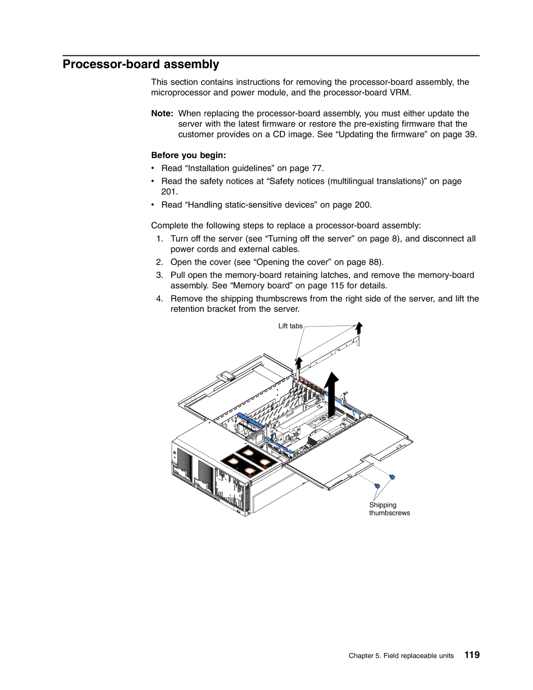
Shipping thumbscrews
Page
Unlocked Locked
Page
Replacing fan 1 or
Replacing and troubleshooting fans
Replacing fan 3 or
Replacing the battery
Do not
Completing the installation
Connecting the cables
Closing the cover
Updating your server configuration
Installing the server in a rack
Page
Memory-board assembly
Memory board
Before you begin
Memory-board voltage regulator module VRM
Close the Dimm access door
Memory switch card and cable
Processor-board assembly
Levers
Microprocessor and power module
Processor-board VRM
PCI-X board assembly
Page
Midplane board
Midplane-board VRM
PCI-X board
Remove any cables that are attached to the PCI-X board
Active PCI assembly
Board, riser card, and Remote Supervisor Adapter
Completed Success
PCI-X
Field replaceable units
Restoring the nonvolatile EFI variables
Select Network Interfaces/Protocols, and press Enter
Click Network Interface
Select Boot Options Maintenance Menu, and press Enter
Page
Top cover assembly
Hard disk drive backplane
Top power board
Media bay card
Memory-board retaining latches
AC box assembly mechanism
Replace FAN Front For Proper
Media-extract mechanism
Light Path card
Power/reset card assembly
Field replaceable units
Page
System-error log is 75% full clear the log
Light Path LED errors
See the system-error log
Before replacing any FRU
PCI-X BUS LED on adapter Check the system-error log
Check Dimm error LED on memory board
Turn off the server and disconnect the ac power cord
Event Log See the system-error log PS1 LED on Power supply
Error
System-error log entries
Ensure that ac power is applied to both power supplies
Information
SAL/EFI messages
Verify Dimm installation order
Error message/symptom FRU/action 187
Reseat DIMMs, re-enable DIMMs, if necessary
Using the Configuration/Setup Utility program,
241
Error message/symptom FRU/action 240
245
247
Update service processor firmware
Error message/symptom FRU/action 1205
Reconfigure PCI/PCI-X adapters
1331
Service processor messages
Microprocessor 3 power module
Service Processor message FRU/action
Microprocessor 2 power module
Microprocessor 4 power module
Remove ac power for 20 seconds, reconnect and reboot
Remove PCI adapters, and see if the problem remains
Ensure microprocessor 1 is properly installed
Disk drives
Remove PCI adapters, and run diagnostics
Diagnostics
Remove PCI adapters and run diagnostics
Check both power supplies are installed and connected to
Reseat DIMMs, re-enable DIMMs, if necessary, using
Check room temperature
Configuration/Setup Utility program, and run diagnostics
Check microprocessor 1-4 power module cable
System-error codes
Diagnostic error codes
Run the Configuration/Setup Utility program
Error Code/Symptom FRU/action
Run Configuration/Setup Utility program
Reseat all PCI devices
Error Code/Explanation FRU/Action
IDE CD test error codes
Manually eject media
Manually close drive
Check drive cables and connections
Atapi removables test error codes
0F03h Read failed
Scsi test error codes
IDE DVD-ROM drive test error codes
Confirm that drive is configured
Code/Explanation FRU/Action
Confirm that drive is formatted and configured
Check if a tape is in drive
Check if write test has been run
Check if a CD is in drive
Manually eject media and close drive
Check if AMIDiag CD is present in drive
USB test error codes
Video test error codes
Check USB keyboard connection
Check USB mouse connection
Check USB hub connection
1302h
Serial port test error codes
Advanced System Management error codes
Hard disk drive backplane
PCI devices on PCI-X card
Light Path card
Memory DIMMs
See the Hardware Maintenance Manual for the RXE-100
RXE port error codes
Xxx-00-00 Restart the server, and run the test again
Memory test error codes
LED error codes
Error symptoms
Memory problems Make sure that
Device drivers are installed correctly
Startup boot microprocessor is not working properly
Reseat microprocessors and power modules
Option problems Make sure that
Symptom Suggested action
Language
Reseat boards, VRMs, and microprocessors
Reseat boards and VRMs
Universal Serial Bus USB Verify that Port problems
Reseat microprocessor
System
Power supply LED errors
Front Power good Good Power on Indicators
Light Midplane Description FRU/action
Diagnostic display error codes
Hardware status error codes
Display report Device
Phase 3 subsystem control status error codes
Error message/explanation FRU/action
SAL/EFI progress codes
Microprocessors
Power-on the server
Scsi error messages
Undetermined problems
Ethernet error messages
Page
System
Parts listing xSeries 450 Type
CRU/FRU
Index XSeries 450 Models 4RX, 5RX, 6RX FRU No
Miscellaneous parts kit 4RX, 5RX, 6 RX
Figure a
Figure B
Keyboard FRU No
Keyboard CRUs
Power cord FRU No
Power cord CRUs
Page
Before you call
Appendix A. Getting help and technical assistance
Software service and support Hardware service and support
General safety
Safety information
Electrical safety
Safety inspection guide
Grounding requirements
Safety notices multilingual translations
To Connect To Disconnect
Do not
≥ 18 kg 39.7 lb ≥ 32 kg 70.5 lb ≥ 55 kg 121.2 lb
Importante
Para Conectar Para Desconectar
Instrução
Cuidado
Instrução
Cuidado
Cuidado
Page
Appendix B. Related service information
Page
Appendix B. Related service information
Page
Appendix B. Related service information
Connexion Déconnexion
Faites-vous aider pour soulever ce produit
Page
Wichtig
Hinweis
Kabel anschlieβen Kabel lösen
Achtung
≥18 kg ≥32 kg
Achtung
Hinweis
Per collegare Per scollegare
Avviso
Attenzione
≥18 kg ≥32 kg
Attenzione
Avviso
Appendix B. Related service information
Page
50 Kg Appendix B. Related service information
Page
Appendix B. Related service information
110
Para la conexin Para la desconexiín
Declaración
Precaución
Precaución
Declaración
Precaución
Edition notice
Appendix C. Notices
Important notes
Trademarks
Product recycling and disposal Battery return program
Industry Canada Class a emission compliance statement
European Union EMC Directive conformance statement
Avis de conformité à la réglementation d’Industrie Canada
Appendix C. Notices
Macedonia former Yugoslav Republic of, Madagascar, Mali
Appendix C. Notices
Page
Index
See also k test read test
SAL/EFI
See Post
Test
Page
Page
Part Number 48P9738