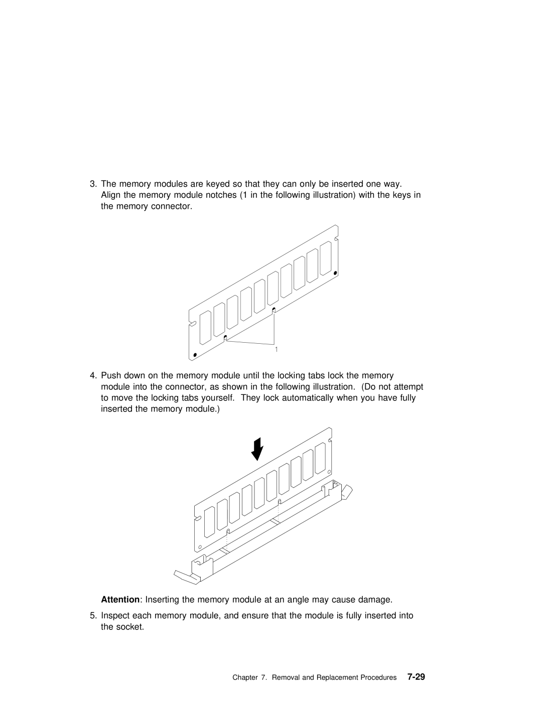
3.The memory modules are keyed so that they can only be inserted one way.
Align the memory module notches (1 in the following illustration) with the keys in the memory connector.
4.Push down on the memory module until the locking tabs lock the memory module into the connector, as shown in the following illustration. (Do not attempt to move the locking tabs yourself. They lock automatically when you have fully inserted the memory module.)
Attention : Inserting the memory module at an angle may cause damage.
5.Inspect each memory module, and ensure that the module is fully inserted into the socket.
Chapter 7. Removal and Replacement Procedures |
