cache space and delivers greater throughput and faster response times for a given cache size.
Additionally, the algorithm modifies dynamically not only the sizes of the two lists, but also the rate at which the sizes are adapted. In a steady state, pages are evicted from the cache at the rate of cache misses. A larger (respectively, a smaller) rate of misses effects a faster (respectively, a slower) rate of adaptation.
Other implementation details take into account the relation of read and write (NVS) cache, efficient destaging, and the cooperation with Copy Services. In this manner, the DS6800 and DS8000 cache management goes far beyond the usual variants of the LRU/LFU (Least Recently Used / Least Frequently Used) approaches.
2.4 Disk subsystem
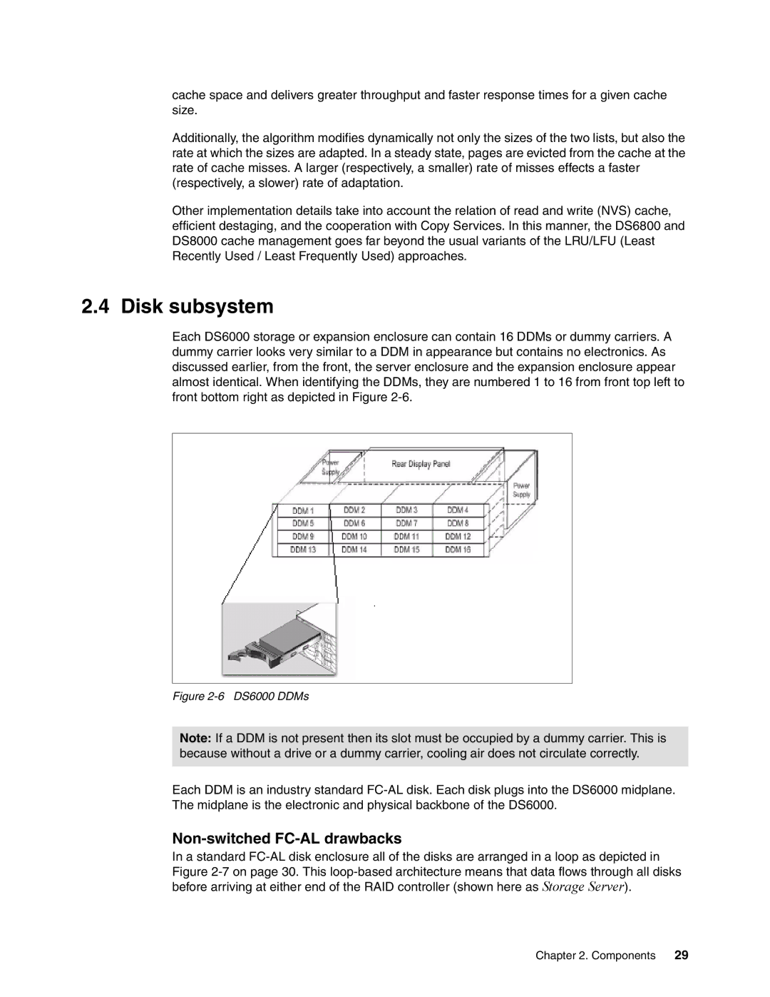
Each DS6000 storage or expansion enclosure can contain 16 DDMs or dummy carriers. A dummy carrier looks very similar to a DDM in appearance but contains no electronics. As discussed earlier, from the front, the server enclosure and the expansion enclosure appear almost identical. When identifying the DDMs, they are numbered 1 to 16 from front top left to front bottom right as depicted in Figure
Figure 2-6 DS6000 DDMs
Note: If a DDM is not present then its slot must be occupied by a dummy carrier. This is because without a drive or a dummy carrier, cooling air does not circulate correctly.
Each DDM is an industry standard
Non-switched FC-AL drawbacks
In a standard
Figure 2-7 on page 30. This loop-based architecture means that data flows through all disks before arriving at either end of the RAID controller (shown here as Storage Server).
Chapter 2. Components 29