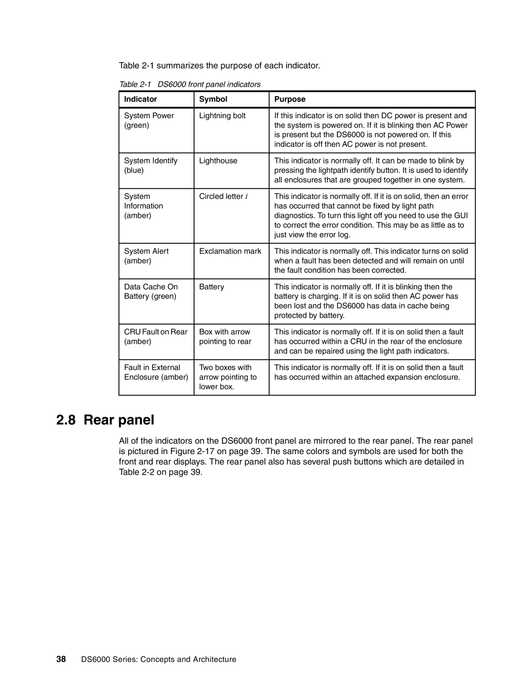
Table 2-1 summarizes the purpose of each indicator.
Table 2-1 DS6000 front panel indicators
Indicator | Symbol | Purpose |
|
|
|
System Power | Lightning bolt | If this indicator is on solid then DC power is present and |
(green) |
| the system is powered on. If it is blinking then AC Power |
|
| is present but the DS6000 is not powered on. If this |
|
| indicator is off then AC power is not present. |
|
|
|
System Identify | Lighthouse | This indicator is normally off. It can be made to blink by |
(blue) |
| pressing the lightpath identify button. It is used to identify |
|
| all enclosures that are grouped together in one system. |
|
|
|
System | Circled letter i | This indicator is normally off. If it is on solid, then an error |
Information |
| has occurred that cannot be fixed by light path |
(amber) |
| diagnostics. To turn this light off you need to use the GUI |
|
| to correct the error condition. This may be as little as to |
|
| just view the error log. |
|
|
|
System Alert | Exclamation mark | This indicator is normally off. This indicator turns on solid |
(amber) |
| when a fault has been detected and will remain on until |
|
| the fault condition has been corrected. |
|
|
|
Data Cache On | Battery | This indicator is normally off. If it is blinking then the |
Battery (green) |
| battery is charging. If it is on solid then AC power has |
|
| been lost and the DS6000 has data in cache being |
|
| protected by battery. |
|
|
|
CRU Fault on Rear | Box with arrow | This indicator is normally off. If it is on solid then a fault |
(amber) | pointing to rear | has occurred within a CRU in the rear of the enclosure |
|
| and can be repaired using the light path indicators. |
|
|
|
Fault in External | Two boxes with | This indicator is normally off. If it is on solid then a fault |
Enclosure (amber) | arrow pointing to | has occurred within an attached expansion enclosure. |
| lower box. |
|
|
|
|
2.8 Rear panel
All of the indicators on the DS6000 front panel are mirrored to the rear panel. The rear panel is pictured in Figure
38DS6000 Series: Concepts and Architecture