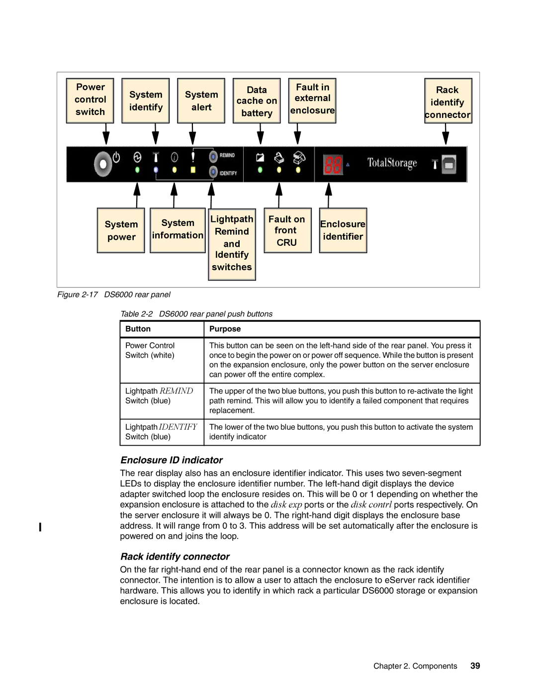
Power | System | System | Data |
| Fault in | Rack | |||||
control | cache on | external | identify | ||||||||
identify | alert |
| |||||||||
switch |
| battery | enclosure | connector | |||||||
|
|
|
|
| |||||||
System | System | Lightpath | Fault on | Enclosure |
| ||||||
| Remind | front |
| ||||||||
| power | information |
| identifier |
| ||||||
|
|
| and | CRU |
| ||||||
|
|
|
|
|
|
|
| ||||
|
|
|
|
| Identify |
|
|
|
| ||
|
|
|
|
| switches |
|
|
|
| ||
Figure |
|
|
|
|
|
|
|
| |||
Table 2-2 DS6000 rear panel push buttons
Button | Purpose |
|
|
Power Control | This button can be seen on the |
Switch (white) | once to begin the power on or power off sequence. While the button is present |
| on the expansion enclosure, only the power button on the server enclosure |
| can power off the entire complex. |
|
|
Lightpath REMIND | The upper of the two blue buttons, you push this button to |
Switch (blue) | path remind. This will allow you to identify a failed component that requires |
| replacement. |
|
|
Lightpath IDENTIFY | The lower of the two blue buttons, you push this button to activate the system |
Switch (blue) | identify indicator |
|
|
Enclosure ID indicator
The rear display also has an enclosure identifier indicator. This uses two
adapter switched loop the enclosure resides on. This will be 0 or 1 depending on whether the expansion enclosure is attached to the disk exp ports or the disk contrl ports respectively. On
the server enclosure it will always be 0. The
Rack identify connector
On the far
Chapter 2. Components 39