Raw or physical DDM layer
At the very top, you can see the raw DDMs. There are four DDMs in a group called a
Array site layer
At the array site level, predetermined groups of four DDMs of the same speed and capacity are arranged. All DDMs reside in the same Disk Enclosure (Array On Loop configuration).
Array layer
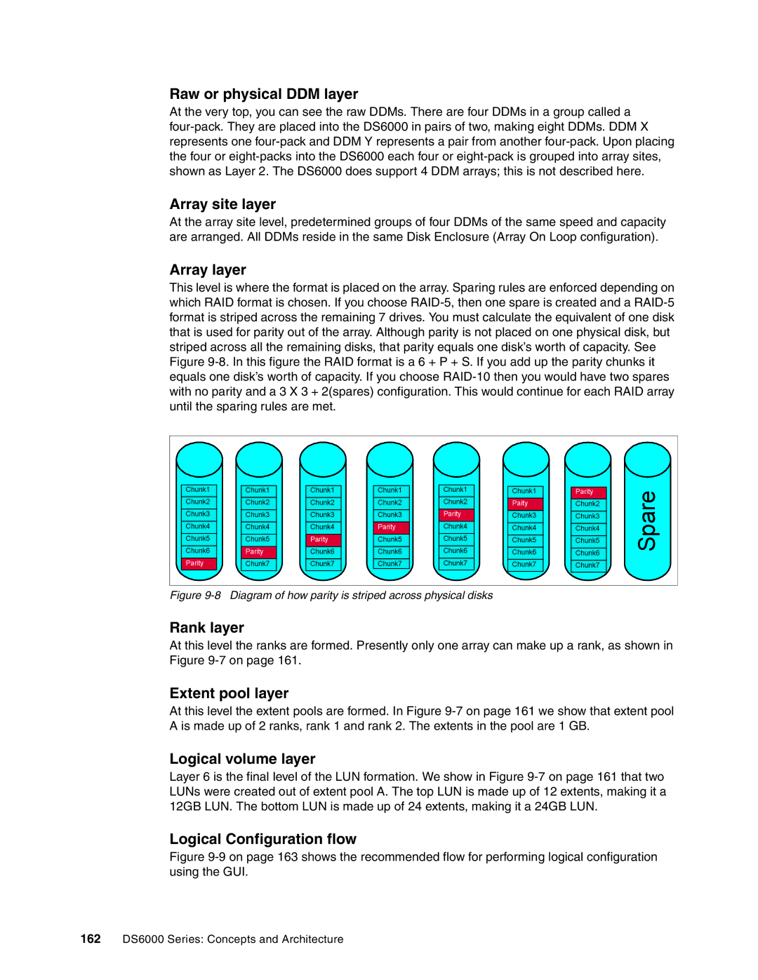
This level is where the format is placed on the array. Sparing rules are enforced depending on which RAID format is chosen. If you choose
Chunk1 |
Chunk2 |
Chunk3 |
Chunk4 |
Chunk5 |
Chunk6 |
Parity |
Chunk1 |
Chunk2 |
Chunk3 |
Chunk4 |
Chunk5 |
Parity |
Chunk7 |
Chunk1 |
Chunk2 |
Chunk3 |
Chunk4 |
Parity |
Chunk6 |
Chunk7 |
Chunk1 |
Chunk2 |
Chunk3 |
Parity |
Chunk5 |
Chunk6 |
Chunk7 |
Chunk1 |
Chunk2 |
Parity |
Chunk4 |
Chunk5 |
Chunk6 |
Chunk7 |
Chunk1 |
Paity |
Chunk3 |
Chunk4 |
Chunk5 |
Chunk6 |
Chunk7 |
Parity | Spare | |
Chunk2 | ||
| ||
Chunk3 |
| |
Chunk4 |
| |
Chunk5 |
| |
Chunk6 |
| |
Chunk7 |
|
Figure 9-8 Diagram of how parity is striped across physical disks
Rank layer
At this level the ranks are formed. Presently only one array can make up a rank, as shown in Figure
Extent pool layer
At this level the extent pools are formed. In Figure
Logical volume layer
Layer 6 is the final level of the LUN formation. We show in Figure
Logical Configuration flow
Figure 9-9 on page 163 shows the recommended flow for performing logical configuration using the GUI.
162DS6000 Series: Concepts and Architecture
