Croma24 Service Manual
7.Insert the Strain Relief (with Trailing Cable) onto the Carrier Assembly by sliding it onto the Strain Relief Support until it snaps firmly into place. See Figure
8.Place the Trailing Cable into the J1 connector lock on the Carrier PCB. Make sure the silver fingers on the Trailing Cable are fully inserted into the lock and slide both sides of the connector lock shut at the same time.
9.Place the right side of the back of the Electronics Cover under the Trailing Cable Support Assembly and gently press down on the ends of the Electronics Cover until the latches snap into the Carrier Assembly.
10.Slide the Carrier Assembly to about the middle of the Slide Shaft and stretch out the Carrier Belt.
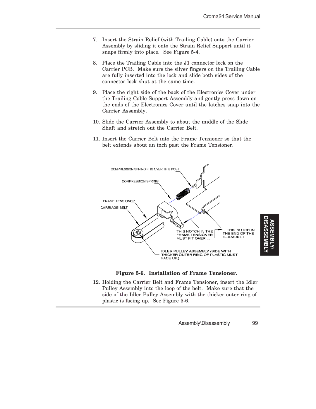
11.Insert the Carrier Belt into the Frame Tensioner so that the belt extends about an inch past the Frame Tensioner.
DISASSEMBLY | ASSEMBLY/ |
|
|
Figure 5-6. Installation of Frame Tensioner.
12.Holding the Carrier Belt and Frame Tensioner, insert the Idler Pulley Assembly into the loop of the belt. Make sure that the side of the Idler Pulley Assembly with the thicker outer ring of plastic is facing up. See Figure