Manuals
/
Integra
/
Computer Equipment
/
Printer
Integra
CROMA24
service manual
Croma24 Assembly Parts Platen and Above
Models:
CROMA24
1
125
132
132
Download
132 pages
60.28 Kb
122
123
124
125
126
127
128
129
Troubleshooting
Specifications
Install
Parts list
General Block Diagram
Material Safety Data Sheet
Quadrature Signal Generation
Warranty
Maintenance
Diagnostics Menu
Page 125
Image 125
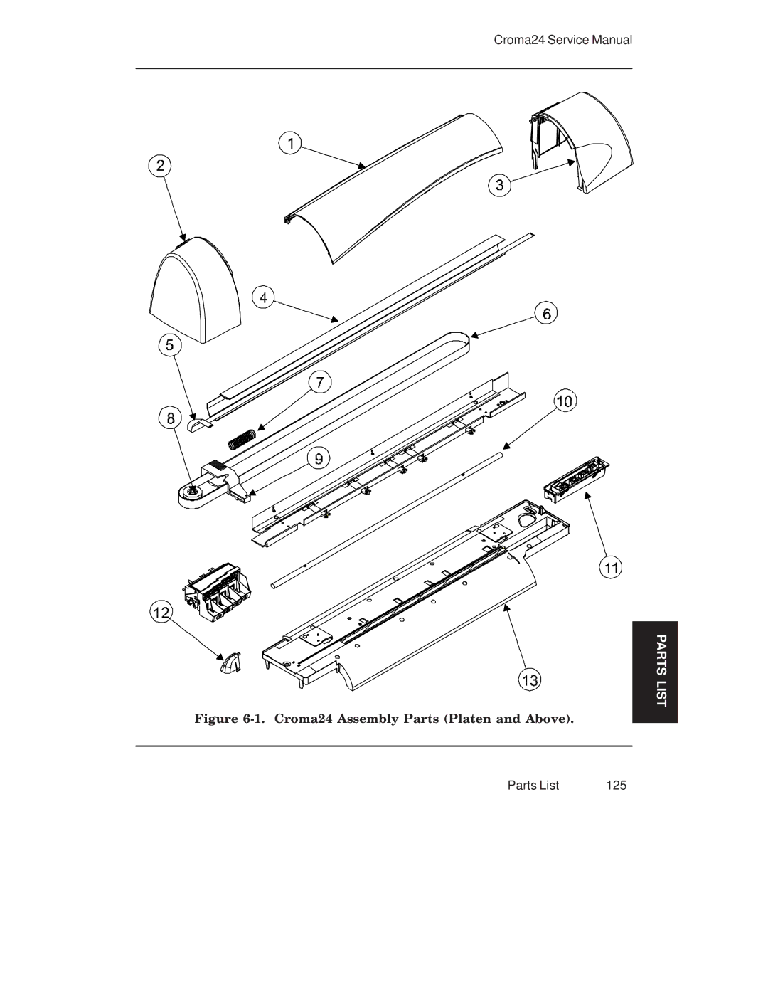
Croma24 Service Manual
Figure
6-1.
Croma24 Assembly Parts (Platen and Above).
PARTS LIST
Parts List
125
Page 124
Page 126
Page 125
Image 125
Page 124
Page 126
Contents
CROMA24
This Page Intentionally Left Blank
Color Inkjet Printer
Printing history
FCC Statement U.S.A
VDE Statement
Material Safety Data Sheet
Warranty or Damage Claims
Table of Contents
Alignments/Adjustments
Troubleshooting
Parts List 123 Index
List of Illustrations
Troubleshooting Assembly/Disassembly
Parts List
List of Tables
Introduction
General Description
Electrostatic Discharge ESD Sensitivity
Overview
Followed by a paragraph describing the concern
Printer Specifications
Description General
General Description
Encad Website
Technical Support
Help Desk Telephone
Help Desk FAX
This Page Intentionally Left Blank
Theory of Operation
General Block Diagram
Paper Media Axis Drive
Carrier Axis Drive
Main Printed Circuit Board Mpcb
Gate Array
Microprocessor
Flash Eeprom
Memory Circuits
Serial Eeprom
Dram
Stepper Motor Controller
Stepper Motor Controller
Servo Motor Controller
Servo Motor Controller
Quadrature Signal Generation
Interface Circuits
Interface Circuits Serial & Parallel
Carrier Assembly Circuits
Power Supply
11. Croma24 System Ground Network Left Side
Front Key Controls
Front Key Control LED Codes
This Page Intentionally Left Blank
Scheduled Maintenance
Maintenance3
Slide Shaft Cleaning
Cleaning Procedures
External Cleaning
Service Station Cleaning
Encoder Strip Cleaning
Linear Encoder Strip Cleaning
Cartridge Dimple Region
Cartridge Dimple Cleaning
Clean and Inspect Stepper Motor Gears
Flex Cable Contact Cleaning
Clean and Inspect Carrier Assembly
Clean and Inspect Mpcb
Mpcb Connection Locations
Reseat Connectors on Mpcb and Carrier Board
Carrier PCB Connection Locations
Replace Carrier Bushings
Servo Motor Winding Resistance Check
Banding Hardware vs Software
Stepper Motor Winding Resistance Check
Examples of Banding
Color Calibration
Alignments/Adjustments
11. Deadband Slow/Fast
Deadband Alignment
Axis Calibration
Pinch Roller Adjustment Procedure
CT IO N ESU LT
Pinch Roller Adjustments
13. Upper Roller Mounting
15. Upper Roller Adjustment
Head Height Alignment Procedure
16. Carrier Head Height Tolerance
18. Zeroing the Micrometer Gauge
20. Carrier Positions for Head Height Adjustment
Maintenance
Croma24 Control Panel
Manufacturing Menu
21. Maintenance Menu
Deadband
Print Quality Test
24. Deadband Slow/Fast Display
Diagnostics Menu
Fan Test
Paper Sensor Test
Color Test
Carriage Vibration Test
Keypad Test Indications
Keypad Test
Servo Motor Test
LED Test
32. Paper Motor Test
Paper Motor Test
33. Service Menu
Service Menu
Built In Test BIT
35. Service Special Information
Firmware/Software Upgrades
Internal Cabling and Signal Flow Diagram
36. Signal Wiring Diagram
No Power
Troubleshooting4
Media Does Not Move
Carrier Axis Failure
Ink Cartridge Misfiring
Does Not Print
Paper Skewing
Printer Output is Banding
Fan Does Not Power Up
This Page Intentionally Left Blank
Assembly\Disassembly5
Remove the Left, Middle Lid, and Right Covers
Assembly\Disassembly
Cover Removal/Installation
Install the Left, Middle, and Right Covers
Assembly\Disassembly
Install the Mpcb and Actuator Assembly
Frame Tensioner
Remove Servo Motor
Disassembly Assembly
Install Servo Motor
Electronics Cover Removal
Strain Relief Removal/Installation from Carrier
Carrier Belt Clamp
Assembly\Disassembly
Installation of Frame Tensioner
Remove the Carrier PCB
Carrier PCB Removal/Installation
Remove the Paper Sensor or the Encoder Sensor
Install the Carrier PCB
Paper and Encoder Sensor Removal
Paper and Encoder Sensor Installation
Install the Paper Sensor or the Encoder Sensor
Remove the Trailing Cable Cover Assembly
10. Trailing Cable Assembly Removal/Installation
Install the Trailing Cable Cover Assembly
11. Carrier Bushing Removal
Replacing the Carrier Bushings
12. Carrier Bushing Installation
13. Service Station, Exploded View
Remove the Service Station, Seals, and Wipers
Install the Service Station, Seals, and Wipers
Remove the Lower Roller Assembly and Stepper Motor
Retnirp
14. C-Bracket Assembly and Platen Removal
15. Stepper Motor Removal/Installation
Install the Lower Roller Assembly and Stepper Motor
16. Installing Lower Roller Assembly
Remove the Power Supply and AC Entry Module
17. Ground Stud With Ground Lugs Attached
18. Power Supply Assembly
Install the Power Supply and AC Entry Module
Disassembly Assembly
This Page Intentionally Left Blank
Parts List
Parts List
124
Croma24 Assembly Parts Platen and Above
Croma24 Assembly Parts Below Platen
Carrier Assembly Breakdown
C-Bracket Assembly Breakdown
Lower Roller Assembly Breakdown
130
Index
Top
Page
Image
Contents