Croma24 Service Manual
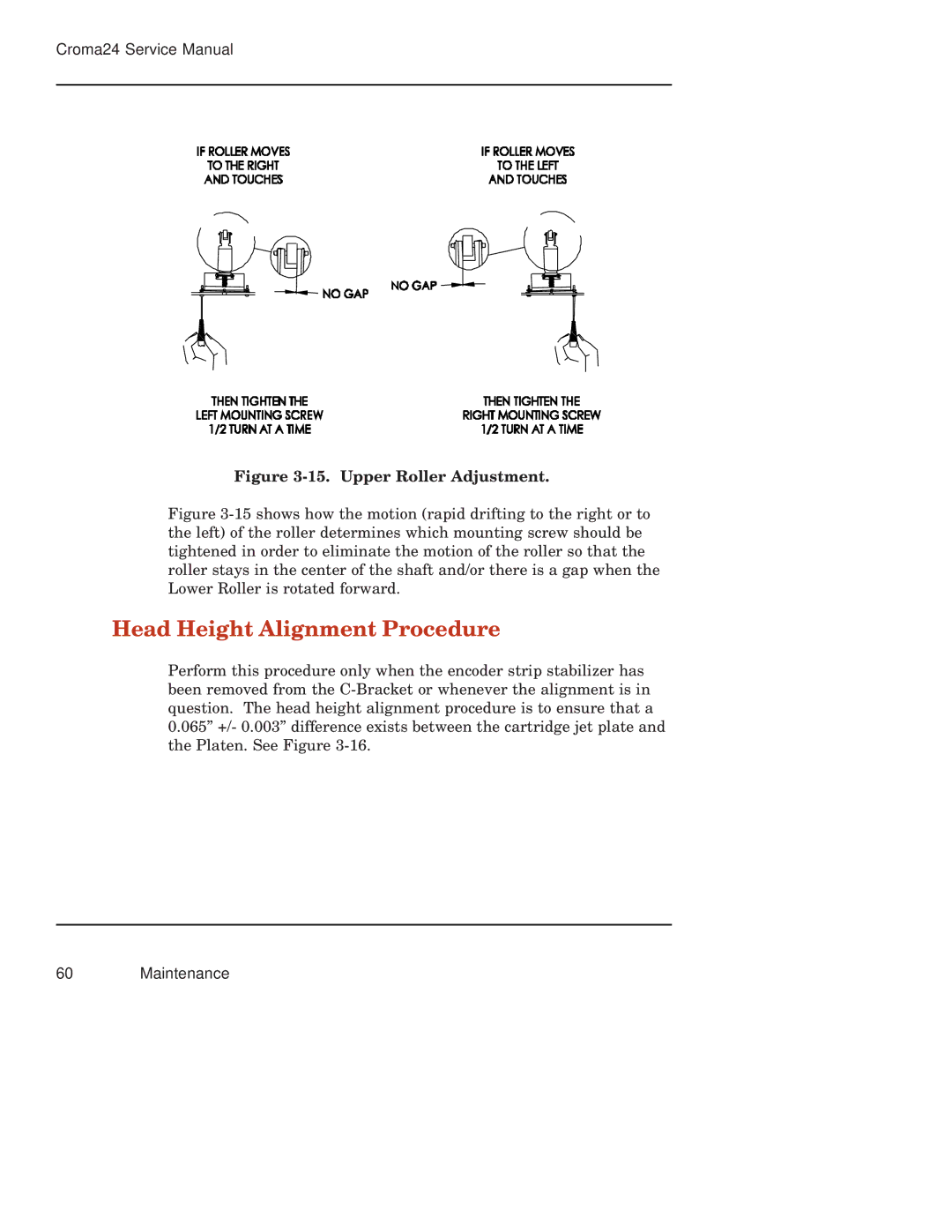
Figure 3-15. Upper Roller Adjustment.
Figure 3-15 shows how the motion (rapid drifting to the right or to the left) of the roller determines which mounting screw should be tightened in order to eliminate the motion of the roller so that the roller stays in the center of the shaft and/or there is a gap when the Lower Roller is rotated forward.
Head Height Alignment Procedure
Perform this procedure only when the encoder strip stabilizer has been removed from the