Croma24 Service Manual
4.Lift up on the front left side of the Electronics Cover until it comes part way off of the Carrier Assembly. Then lift up on the front right side of the Electronics Cover and move the Electronics Cover slightly to the left so that the back of it clears the Trailing Cable Support Assembly. See Figure
5.Lift up on the connector lock to unlock the Trailing Cable connector (J1) on the Carrier PCB and remove the end of the Trailing Cable.
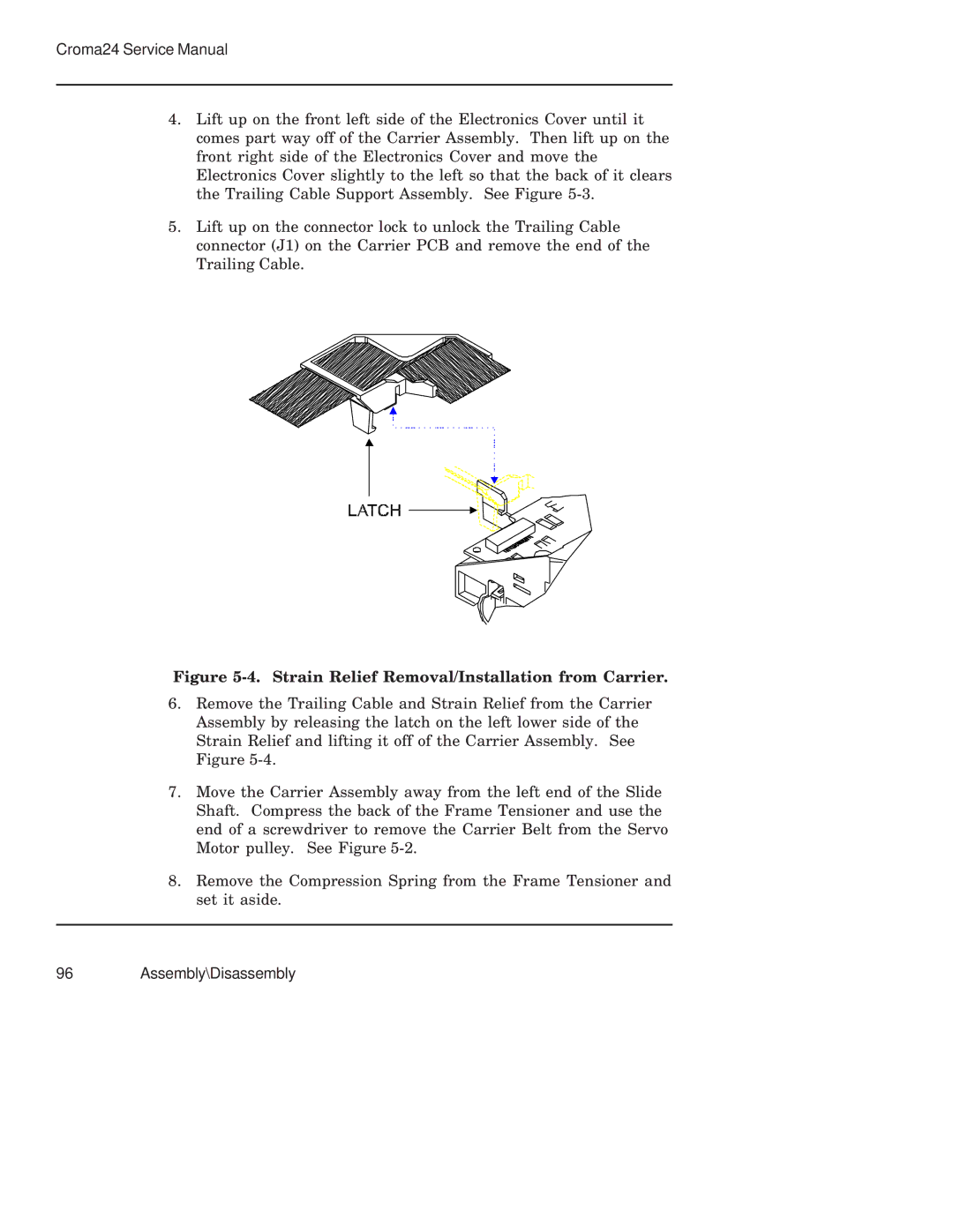
Figure 5-4. Strain Relief Removal/Installation from Carrier.
6.Remove the Trailing Cable and Strain Relief from the Carrier Assembly by releasing the latch on the left lower side of the Strain Relief and lifting it off of the Carrier Assembly. See Figure
7.Move the Carrier Assembly away from the left end of the Slide Shaft. Compress the back of the Frame Tensioner and use the end of a screwdriver to remove the Carrier Belt from the Servo Motor pulley. See Figure
8.Remove the Compression Spring from the Frame Tensioner and set it aside.
