Croma24 Service Manual
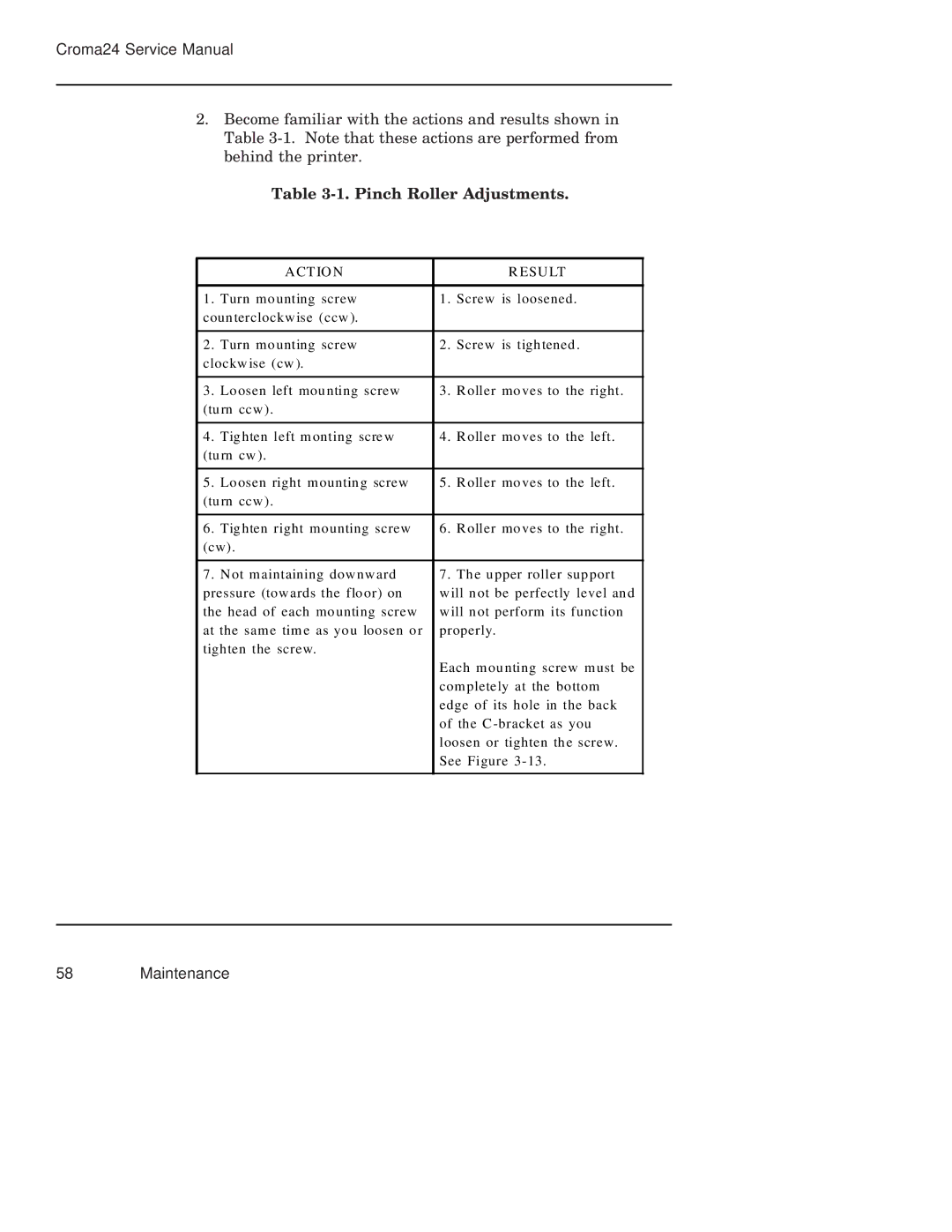
2.Become familiar with the actions and results shown in Table
Table 3-1. Pinch Roller Adjustments.
| A CT IO N |
| R ESU LT |
|
|
|
|
1. | Turn mo unting screw | 1. | Screw is loosened. |
coun terclockw ise (ccw ). |
|
| |
|
|
|
|
2. | Turn mo unting screw | 2. | Screw is tigh tened . |
clockw ise (cw ). |
|
| |
|
|
|
|
3. | Lo osen left mou nting screw | 3. | R oller mo ves to the right. |
(tu rn ccw ). |
|
| |
|
|
|
|
4. | Tig hten left m onting scre w | 4. | R oller mo ves to the left. |
(tu rn cw ). |
|
| |
|
|
|
|
5. | Lo osen right m ountin g screw | 5. | R oller mo ves to the left. |
(tu rn ccw ). |
|
| |
|
|
|
|
6. | Tig hten right mo unting screw | 6. | R oller mo ves to the right. |
(cw). |
|
| |
|
|
|
|
7. | N ot m aintaining dow nw ard | 7. | Th e u pper roller sup port |
pressure (tow ards the flo or) on | w ill n ot be perfectly level an d | ||
the head of each mo unting screw | w ill n ot perform its func tion | ||
at the sam e tim e as yo u loosen o r | properly. | ||
tigh ten the screw. |
|
| |
|
| Each m ou nting screw m ust be | |
|
| com plete ly at the bo ttom | |
|
| edge of its hole in the back | |
|
| of th e C | |
|
| loosen or tighten th e screw. | |
|
| See Figure | |
|
|
|
|