Croma24 Service Manual
Stepper Motor Controller
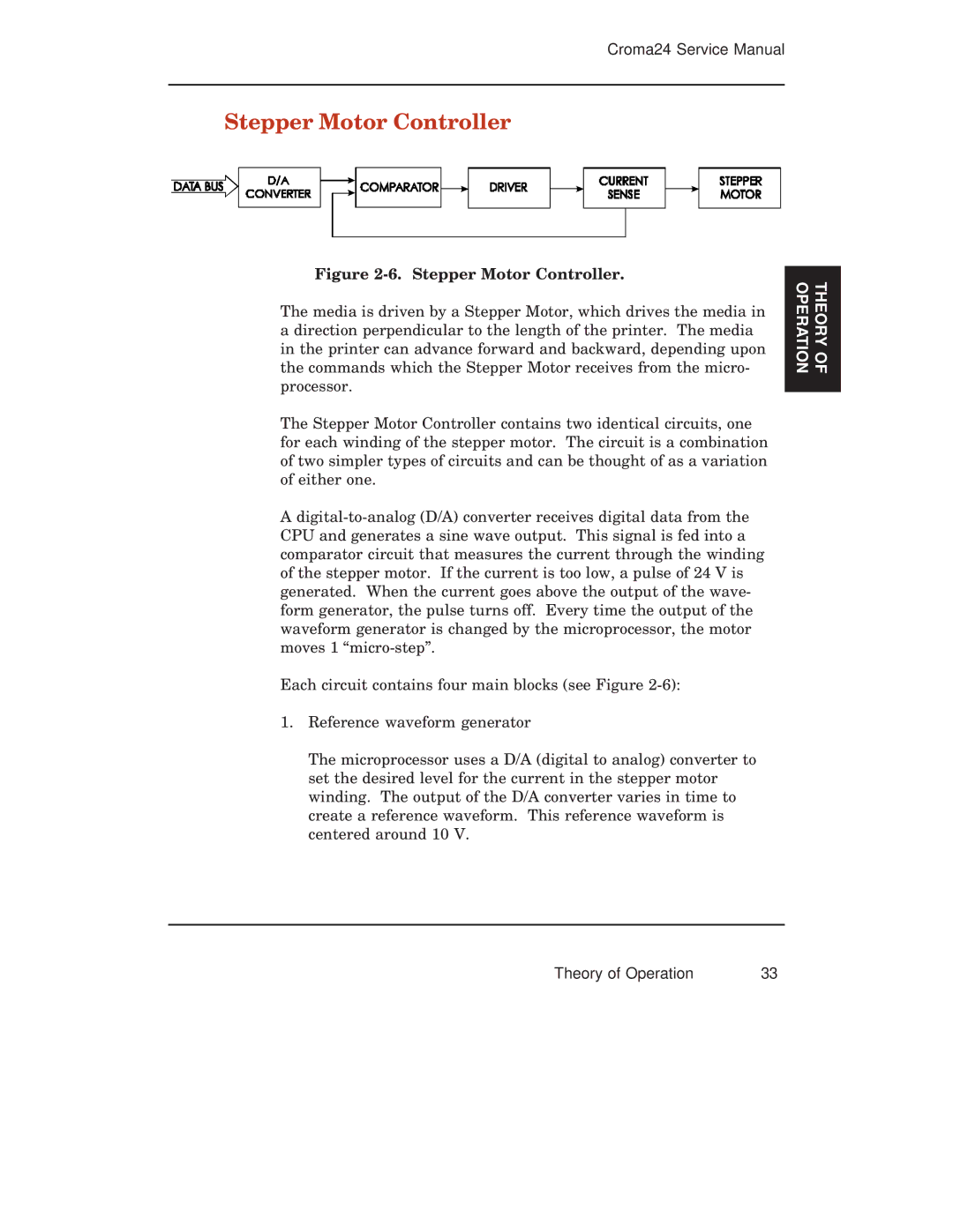
Figure 2-6. Stepper Motor Controller.
The media is driven by a Stepper Motor, which drives the media in a direction perpendicular to the length of the printer. The media in the printer can advance forward and backward, depending upon the commands which the Stepper Motor receives from the micro- processor.
The Stepper Motor Controller contains two identical circuits, one for each winding of the stepper motor. The circuit is a combination of two simpler types of circuits and can be thought of as a variation of either one.
A
Each circuit contains four main blocks (see Figure
1. Reference waveform generator
THEORY OF OPERATION
The microprocessor uses a D/A (digital to analog) converter to set the desired level for the current in the stepper motor winding. The output of the D/A converter varies in time to create a reference waveform. This reference waveform is centered around 10 V.
Theory of Operation | 33 |
