Leica DMI3000B Leica DMI4000B Leica DMI6000B
MQM-Hotline@leica-microsystems.com
Leica DMI3000B Leica DMI4000B Leica DMI6000B
Copyrights
Copyrights
Contents
Differential
Important Notes about this Manual
Important Notes about this Manual
→ p
Intended Purpose of the Microscope
Intended Purpose of the Microscope
Safety Notes
Safety Notes
General Safety Notes
Leica CTR4000, CTR6000 and CTR6500 electron- ics boxes
Microscope
Ebq 100 supply unit
Ambient temperature 15Ð35C
Overview of the Leica DMI Series
Specifications Contrast Methods
Overview of the Instrument
Leica DMI Series
Incident light axis
Tube
Objective Turret
Stages
Overview of the Instrument Objective Turret
Condensers
Focus
Observation ports
Overview of the Instrument Observation ports
Controls
Electronics box
Software tools
Overview of the Instrument Interfaces
Overview of the Instrument
Field diaphragm centering fluorescence microscopes only
Overview of the Instrument
SmartMove remote control module
Overview of the Instrument
Overview of the Instrument
Overview of the Instrument
Overview of the Instrument
Unpacking the Microscope
Unpacking the Microscope
Installation location
Unpacking the Microscope Transport
Assembly
Assembly Tools
Assembling the Microscope
→ Ch .10, p
Assembly Installation
¥ Release the two socket screws and remove the prism disk
Replacing individual IC prisms
Mechanical 3-plate stage
Assembly Installation of Specimen Stages
Fixed micromanipulation stage Micromanipulation stage
B, c
Fixed stage
Manual fixed micromanipulation stage
Manual fixed micromanipulation stage
Able mechanical stage of the standard stage
Insert frames a to c differ at this
Assembly Motorized 3-plate or scanning stages
Rotating Stage and Insert Frames for Coverslips
¥ Switch the microscope off
Assembly Installation of Condensers
¥ Next, take the special condenser tool Fig
Phase rings
Condenser
Installation of IC prisms
Installation of Condensers
Condenser on transmitted-light illumination arm
Assembly Condenser heads
Assembly Installation of eyepieces
Installation of objectives
Eyepieces are inserted into the eyepiece tubes
Lamp housing cabling cable duct
Installing the transmitted-light lamp housing
Changing the 12 V 100 W halogen lamp
Case the lamp has to be removed
Right Wrong
Booster lens in stand
Lamp housing 106 z L with Hg 100 W lamp
Lamp housing 106 z
Type
Hg 100a Xe 75b
Assembly Make sure to follow the safety notes on
¥ Install the burner in reverse order
Xe 75 burner
Assembly
Opening the fluorescence drawer 1 Analyzer slot
Assembly Equipping the Incident Light Turret Disc
Replacing cubes with the instrument switched on
Load
To insert the cubes, proceed exactly as de- scribed above
Installation of the polarizer and analyzer
Assembly Inserting the Front Module Slider
Analyzer slot cap
Assembly Analyzer for incident light and transmitted light
Mount
Assembly Optional Accessories Camera
Direct interface socket optional
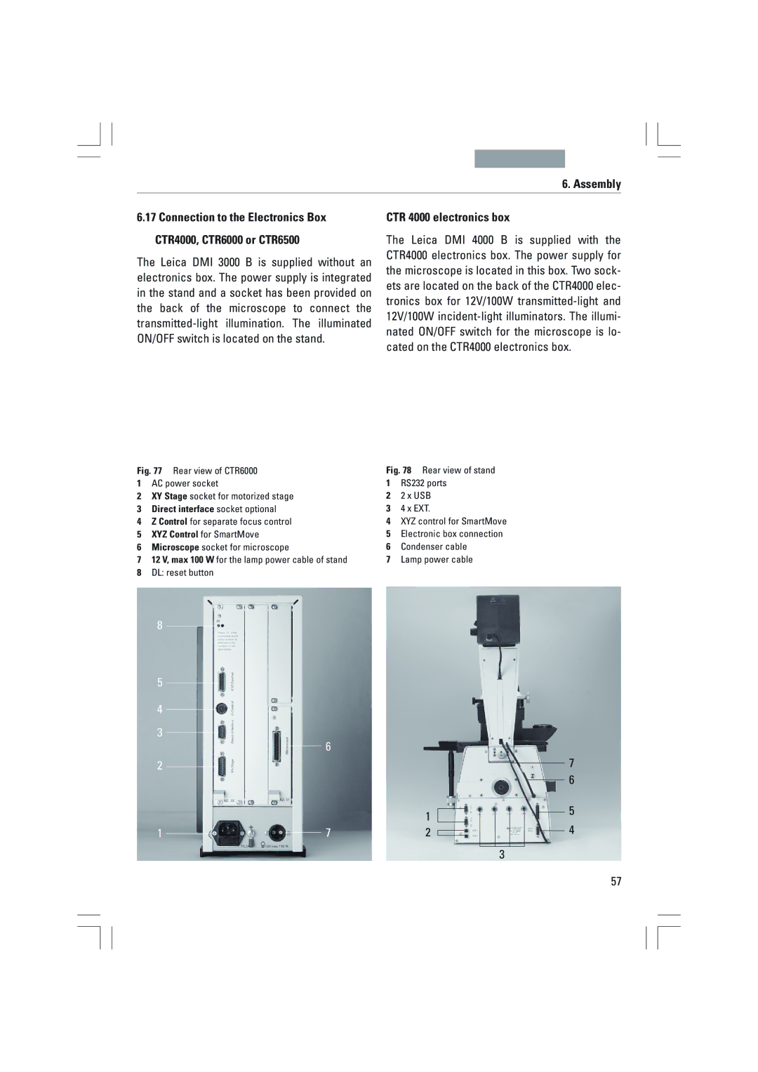
CTR 4000 electronics box
Connection to the Power Supply
Assembly CTR6000 and CTR6500 electronics box
Start-up
Start-up
Functional Principle Leica DMI4000 B and Leica DMI6000 B
Intelligent automation
Start-up
Function Fixed Variable
ICT
Start-up Switching on the Microscope
Features of the individual microscope
Start-up LeicaDisplay
Leica DMI 4000 B and DMI 6000 B
Fixed function buttons on the left side
Start-up Function Buttons on the Stand
Possible functions
Start-up Variable function buttons on the stand
ExMan
Fine only DMI6000B
Focus buttons DMI6000 B only
Variable function buttons on SmartMove
Preparation ¥ Configure the microscope as follows
Start-up
Start-up
Adjusting the field diaphragm incident light-fluorescence
Adjusting the field diaphragm
Regular phase contrast with phase objectives
Start-up Checking Phase Contrast Rings
Start-up
Start-up
Start-up Checking modulation contrast slit diaphragms
Setting the Motorized Polarizer
Reflector cube for lamp adjustment
Lamp housing 107 L For 12V 100W halogen lamp
¥ Focus the direct image with the collector
Centering the Hg 100 W and Xe 75 W mercury lamps
Start-up
If a PC is connected, switch on the electronics
Switching on
Operation
Operation
LeicaScreen following initialization
Bright Field TL
Operation Contrast Methods
Operation
Operation Phase Contrast TL Integrated phase contrast, see
Operation Dark Field TL
Manual method
Operation Polarization TL
Motorized method
Combined methods
Manual alternative
DIC disk with knurled wheel for fine adjustment
Operation Integrated Phase Contrast TL
Integrated Modulation Contrast TL
Leica Application Suite LAS Software
Changing the fluorescence filter cube
Options
Is facing forward
Scope
Leica DMI4000 and DMI6000 B
Suitable objective
Transmitted illumination is activated
Focusing the image
Operation Focusing
Setting stops
Leica Application Suite LAS
Switch between Fine and Coarse via
Setting the step increments
Operation Set the stops via
Going to the stops
Adjusting the viewing angle
Adjusting the viewing distance
Operation Tubes
Beam splitting in photo tubes
Correction for Vision Problems
Operation Eyepieces
Eyepieces with inlaid reticle
Change operating mode via
Changing the operating mode
OIL only use optical immersion oil
Select objectives via
Gray
Color coding of objectives
White water
Orange glycerin
Object displacement using SmartMove
Operation Stages and Object Displacement
Switch between Precise and Fast via
Storing and restoring stage positions
Magnification Changer
Adjust intensity via
Fine adjustment
Operation Light sources
¥ For TL and IL
Adjust diaphragms via
Troubleshooting Aperture and Field Diaphragm
Problem Cause/Remedy Stand
Troubleshooting
Power supply
Lamp does not illuminate immediately upon being switched on
Dark Field
Troubleshooting Problem Cause/Remedy Bright field
No definite DF contrast is possible
→ p
Troubleshooting Problem Cause/Remedy Phase contrast
Polarization
Transmitted light interference contrast
LeicaScreen
Troubleshooting Problem Cause/Remedy Fluorescence
106
Troubleshooting
Cleaning Coated Parts
Dust Cover Cleaning
Cleaning the stage
Pflege des Mikroskops
Cleaning Objectives
Pflege des Mikroskops Cleaning Glass Surfaces
Removing Immersion Oil
Handling Acids and Bases
Major Consumable and Replacement Parts
Major Consumable and Replacement Parts
109
Dimensions
Dimensions
Space requirements Height compensation plate
110
Abbreviations and Icons
Abbreviations and Pictograms
Abbreviations and Icons Aperture diaphragm Bright field
Integrated phase contrast
Combination method
Fluo cube
Index
Index
Glass insert Lamp housing 107 L Objectives 17, 60 Graticule
Object displacement
Lamp housing for incident Stand
Phase contrast
Tube 12, 16, 84 Tube setting 84 Turret disk
EU Declaration of Conformity
EU Declaration of Conformity
Leica DMI3000B Leica DMI4000B Leica DMI6000B
Copyrights
Copyrights
Inhalt
Inhalt
Differentieller
Wichtigste Verschlei§
Aperturblende und
Wichtige Hinweise zur Anleitung
Wichtige Hinweise zur Anleitung
Achtung
→ S
Zweckbestimmung des Mikroskops
Zweckbestimmung des Mikroskops
Sicherheitshinweise
Sicherheitshinweise
Allgemeine Sicherheitshinweise
Elektronikbox Leica CTR4000, CTR6000 und CTR6500
Mikroskop
VorschaltgerŠt ebq
Sicherheitshinweise Achtung
GerŠteŸbersicht
Geräteübersicht Leica DMI-Serie
Spezifikationen Kontrastverfahren
Durchlichtachse
Auflichtachse
Tubus
Objektivrevolver
Tische
GerŠteŸbersicht Objektivrevolver
Fokus
Kondensoren
Elektronikbox
Bedienelemente
Software tools
GerŠteŸbersicht Schnittstellen
GerŠteŸbersicht
Variable Funktionstasten
GerŠteŸbersicht
Abb a Frontbedienfeld
GerŠteŸbersicht
GerŠteŸbersicht
GerŠteŸbersicht
GerŠteŸbersicht
Auspacken
Auspacken
Der Stativkarton enthŠlt die folgenden Kompo- nenten
Hinweis
Aufstellungsort
Auspacken Transport
Montage
Montage des Mikroskops
Lesen Sie dazu das Kapitel Ã6.16 Optionales ZubehšrÒ → S
Montagewerkzeug
Montage des Durchlicht-BeleuchtungstrŠgers DL
NachrŸstung einzelner IC-Prismen
Bei NachrŸstung der IC-Prismenscheibe wie folgt vorgehen
Montage Montage der Objekttische
Mit und ohne ObjektfŸhrer
¥ Manueller Drehtisch
Abb Fester Mikromanipulationstisch
Fester Tisch
Montage Manueller fester Mikromanipulationstisch
Des normalen Tisches
Oder durch Lšsen der Schrauben gewechselt
Motorische 3-Platten oder Scanningtische
Unbedingt die FederbŸgel nur seitlich andrŸk- ken
Drehtisch und Einlegerahmen fŸr DeckglŠser
¥ Schalten Sie das Mikroskop aus
Montage Montage der Kondensoren
Unter den FederbŸgel der Aufnahme greift Abb
¥ Nehmen Sie nun die spezielle Kondensor- zange zu Hand Abb
Montage IC-Kondensorprismen
Das Prisma ist so einzusetzen Kondensor
Unter den FederbŸgel der Aufnahme greift Abb a
Schalten des Mikroskops mit Hilfe der
Montage Achtung
Montage Kondensorkšpfe
Die Okulare werden in die Okularstutzen einge- setzt
Montage Einsetzen der Okulare
Einsetzen der Objektive
Deshalb šfters die Frontlinse auf Sauberkeit prŸfen
Elektronikbox Leica CTRxxxx an Abb Leica DMI3000 B
Montage des Durchlicht-Lampenhauses
Abb a Abb c
¥ Entfernen Sie die SchutzhŸlle der Lampe
Richtig b falsch
Je nach Orientierung des Schiebers
Symbol sichtbar
Lampenhaus 106 z
Montage Montage und Wechsel der Auflichtlampen Achtung
Typ
Hg 100aXe 75b
¥ Setzen Sie den Brenner in umgekehrter Rei- henfolge ein
Achtung Xe 75-Brenner
SchutzhŸlle des Brenners 61.4 nach dem Einbau entfernen
Der Brenner muss nach dem ZŸnden sofort justiert werden
BestŸckung der Auflicht-Revolverscheibe
Load
Wechseln der WŸrfel im eingeschalteten Zu- stand
Einsetzen des Front-Modul Schiebers
Montage Durchlicht- und Auflichtanalysator
Montage Optionales Zubehšr Kamera
Elektronikbox CTR
Montage Elektronikbox CTR6000 und CTR6500
HinweisHinweis
Anschluss an die Stromversorgung
Inbetriebnahme
Inbetriebnahme
Funktionsprinzip Leica DMI4000 B und Leica DMI6000 B
Intelligente Automatisierung
Hinweis Reset-Funktion
Den kšnnen
Das Mikroskop kann auf die werkseitig pro
Funktion
ICT
Inbetriebnahme Einschalten
Leica DMI 4000 B und DMI 6000 B
Inbetriebnahme Das LeicaDisplay
Fest definierte Funktionstasten auf der linken Stativseite
Inbetriebnahme Die Funktionstasten am Stativ
ExMan
Inbetriebnahme Variable Funktionstasten am Stativ
Fine nur DMI6000B
Coarse nur DMI6000 B
Fokus-Bedientasten Abb nur DMI6000 B
SET + Z″
SET + Z
Variable Funktionstasten am SmartMove
Das Fernsteuermodul SmartMove Drehknšpfe am SmartMove
Kšhlersche Beleuchtung nicht fŸr S70 Kondensor
Nun beginnt die eigentliche Kšhler-Beleuch- tung
Durchmesser jedoch zu klein
Justieren der Leuchtfeldblende
Inbetriebnahme Phasenkontrastringe ŸberprŸfen
¥ Fokussieren Sie das PrŠparat
Inbetriebnahme
Einstellung des motorischen Polarisators
Inbetriebnahme Modulationskontrast Schlitzblenden ŸberprŸfen
Lampenhaus 107 L FŸr HalogenglŸhlampe 12 V 100 W
Inbetriebnahme Achtung
Zentrieren der Quecksilberlampen Hg 100 W und Xe 75 W
¥ Stellen Sie das direkte Bild mit dem Kollektor scharf
Inbetriebnahme
Bedienung
Bedienung
Computer ein
Verfahren weiter
Bedienung
Hellfeld TL
Bedienung Kontrastverfahren
Bedienung
Hinweise
Bedienung Phasenkontrast TL
Bedienung Dunkelfeld TL Hinweise
¥ WŠhlen Sie das Kontrastverfahren POL Pola- risation
Bedienung Polarisation TL
Manuelles Verfahren
Motorisches Verfahren
Manuelle Alternative
Leica DMI3000 B ¥ WŠhlen Sie ein Objektiv
Bedienung Integrierter Phasenkontrast TL
Alternativ DrŸcken Sie die variable Taste
Nach vorne zeigt
Optionen
Wechsel des Fluoreszenz-FilterwŸrfels
Feste Funktionstasten am Frontbedien
Bedienung Kombi-Verfahren Leica DMI4000 und DMI6000 B
Die Durchlichtbeleuchtung ist aktiviert
Die Fluoreszenzbeleuchtung ist aktiviert
Bild fokussieren
Bedienung Fokussierung
Den
Schwellen setzen
Anfahren der Schwellen
Bedienung Setzen der Schwellen Ÿber
Anfahren der Schwellen Ÿber
Einstellen der Schrittweiten
Augenabstand einstellen
Bedienung Tuben Hinweis
Einblickwinkel einstellen
Strahlenteilung bei Fototuben
Bedienung Okulare Hinweis
Okulare mit eingelegter Strichplatte
Korrektur bei Fehlsichtigkeit
Anfahren der Objektive Ÿber
Sicherheitsdatenblatt zum Immersionsšl be- achten
Wechsel des Betriebsmodus
Betriebsmodus wechseln Ÿber
Farbkennung der Objektive
Bedienung HinweisHinweis
150x 160x Wei§
Rot
Objektverschiebung Ÿber SmartMove
Bedienung Tische und Objektverschiebung
Umschalten zwischen Precise und Fast Ÿber
Tischpositionen speichern und anfahren
Vergrš§erung wechseln Ÿber
Bedienung Vergrš§erungswechsler
¥ Bei TL und IL
Bedienung Lichtquellen
Licht einstellen Ÿber
100
Blenden einstellen Ÿber
Trouble Shooting Aperturblende und Leuchtfeldblende
Trouble Shooting
Problem Ursache/Abhilfe Stativ
Beleuchtung
Trouble Shooting
Problem Ursache/Abhilfe Hellfeld
Dunkelfeld
Trouble Shooting Problem Ursache/Abhilfe Phasenkontrast
Polarisation
Durchlicht-Interferenzkontrast
LeicaDisplay
Problem Ursache/Abhilfe Fluoreszenz
106
Pflege des Mikroskops
Reinigen von Objektiven Achtung
Pflege des Mikroskops Reinigen von GlasflŠchen
Entfernen von Immersionsšl Achtung
Umgang mit SŠuren und Basen
Wichtigste Verschleiß- und Ersatzteile
Wichtigste Verschlei§- und Ersatzteile
109
Abmessungen
Abmessungen
Platzbedarf Hšhenausgleichsplatte
110
AbkŸrzungen und Piktogramme
Abkürzungen und Piktogramme
Phasenkontrast
Integrierter Phasenkontrast
Hellfeld
Kombinationsverfahren
Index
Index
Initialisierung Des Stativs
Lampenversorgungskabel
Leica-Zugriff Fokus
Kamera Leuchtfeldblenden
10, 46, 47, 54
EU-KonformitŠtserklŠrung
EU-Konformitätserklärung
Page
Ordernos.oftheeditionsinEnglish/German/French933000