NXP Semiconductors
DRAFT | D | D |
| AFT |
RAFT | RAFT AFT | |||
|
|
| DR | DR |
DLPC2917/19
ARM9 microcontrollerRAFT withDRAFTCANDRAFTand LINDRAFT
| DRA | DRA |
| DR | |
| F | F |
| ||
8.7.6.4 Master and slave mode | T DRAFT | T |
| ||
DRAFT DRAFT DRAF | |||||
| |||||
A PWM module can provide synchronization signals to other modules (also called Master |
|
| |||
mode). The signal sync_out is a pulse of one clock cycle generated when the internal |
|
| |||
| DRAFT DRAFT | ||||
PWM counter (re)starts. The signal trans_enable_out is a pulse synchronous to sync | out, |
| D | ||
generated if a transfer from system registers to PWM shadow registers occurred when the |
| ||||
|
| ||||
PWM counter restarted. A delay may be inserted between the counter start and | DRAFT |
| |||
| DRA | ||||
generation of trans_enable_out and sync_out. |
|
| |||
A PWM module can use input signals trans_enable_in and sync_in to synchronize its internal PWM counter and the transfer of shadow registers (Slave mode).
8.7.6.5 PWM pin description
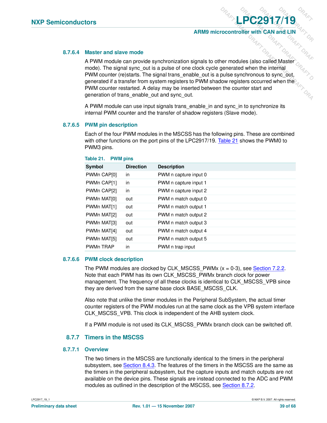
Each of the four PWM modules in the MSCSS has the following pins. These are combined with other functions on the port pins of the LPC2917/19. Table 21 shows the PWM0 to PWM3 pins.
Table 21. PWM pins
Symbol | Direction | Description |
PWMn CAP[0] | in | PWM n capture input 0 |
|
|
|
PWMn CAP[1] | in | PWM n capture input 1 |
|
|
|
PWMn CAP[2] | in | PWM n capture input 2 |
|
|
|
PWMn MAT[0] | out | PWM n match output 0 |
|
|
|
PWMn MAT[1] | out | PWM n match output 1 |
|
|
|
PWMn MAT[2] | out | PWM n match output 2 |
|
|
|
PWMn MAT[3] | out | PWM n match output 3 |
|
|
|
PWMn MAT[4] | out | PWM n match output 4 |
|
|
|
PWMn MAT[5] | out | PWM n match output 5 |
|
|
|
PWMn TRAP | in | PWM n trap input |
|
|
|
8.7.6.6PWM clock description
The PWM modules are clocked by CLK_MSCSS_PWMx (x =
Also note that unlike the timer modules in the Peripheral SubSystem, the actual timer counter registers of the PWM modules run at the same clock as the VPB system interface CLK_MSCSS_VPB. This clock is independent of the AHB system clock.
If a PWM module is not used its CLK_MSCSS_PWMx branch clock can be switched off.
8.7.7Timers in the MSCSS
8.7.7.1Overview
The two timers in the MSCSS are functionally identical to the timers in the peripheral subsystem, see Section 8.4.3. The features of the timers in the MSCSS are the same as the timers in the peripheral subsystem, but the capture inputs and match outputs are not available on the device pins. These signals are instead connected to the ADC and PWM modules as outlined in the description of the MSCSS, see Section 8.7.2.
LPC2917_19_1 | © NXP B.V. 2007. All rights reserved. |
Preliminary data sheet | Rev. 1.01 — 15 November 2007 | 39 of 68 |