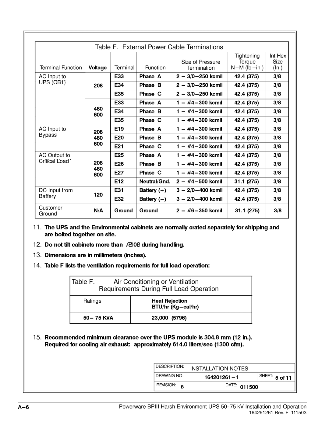
Table E. External Power Cable Terminations
|
|
|
|
|
|
| Tightening | Int Hex | |
|
|
|
|
| Size of Pressure | Torque | Size | ||
Terminal Function | Voltage | Terminal | Function |
| Termination | N | (In.) | ||
|
|
|
|
|
|
|
|
| |
AC Input to |
| E33 | Phase ‘A’ | 2 | 42.4 (375) | 3/8 | |||
UPS (CB1) |
|
|
|
|
|
|
|
| |
208 | E34 | Phase ‘B’ | 2 | 42.4 (375) | 3/8 | ||||
| |||||||||
|
|
|
|
|
|
|
|
| |
|
| E35 | Phase ‘C’ | 2 | 42.4 (375) | 3/8 | |||
|
|
|
|
|
|
|
|
| |
| 480 | E33 | Phase ‘A’ | 1 | 300 kcmil | 42.4 (375) | 3/8 | ||
|
|
|
|
|
|
|
| ||
| E34 | Phase ‘B’ | 1 | 300 kcmil | 42.4 (375) | 3/8 | |||
| 600 | ||||||||
|
|
|
|
|
|
|
| ||
| E35 | Phase ‘C’ | 1 | 300 kcmil | 42.4 (375) | 3/8 | |||
|
| ||||||||
|
|
|
|
|
|
|
|
| |
AC Input to | 208 | E19 | Phase ‘A’ | 1 | 300 kcmil | 42.4 (375) | 3/8 | ||
Bypass |
|
|
|
|
|
|
| ||
480 | E20 | Phase ‘B’ | 1 | 300 kcmil | 42.4 (375) | 3/8 | |||
| |||||||||
| 600 |
|
|
|
|
|
|
| |
| E21 | Phase ‘C’ | 1 | 300 kcmil | 42.4 (375) | 3/8 | |||
|
| ||||||||
|
|
|
|
|
|
|
|
| |
AC Output to |
| E25 | Phase ‘A’ | 1 | 300 kcmil | 42.4 (375) | 3/8 | ||
Critical Load | 208 |
|
|
|
|
|
|
| |
E26 | Phase ‘B’ | 1 | 300 kcmil | 42.4 (375) | 3/8 | ||||
| |||||||||
| 480 |
|
|
|
|
|
|
| |
| E27 | Phase ‘C’ | 1 | 300 kcmil | 42.4 (375) | 3/8 | |||
| 600 | ||||||||
|
|
|
|
|
|
|
| ||
|
| E12 | Neutral/Gnd. | 2 | 500 kcmil | 31.1 (275) | 3/8 | ||
|
|
|
|
|
|
|
|
| |
DC Input from | 120 | E31 | Battery (+) | 3 | 42.4 (375) | 3/8 | |||
Battery |
|
|
|
|
|
|
| ||
E32 | Battery | 3 | 42.4 (375) | 3/8 | |||||
|
| ||||||||
|
|
|
|
|
|
|
|
| |
Customer | N/A | Ground | Ground | 2 | 350 kcmil | 31.1 (275) | 3/8 | ||
Ground | |||||||||
|
|
|
|
|
|
|
| ||
11.The UPS and the Environmental cabinets are normally crated separately for shipping and are bolted together on site.
12.Do not tilt cabinets more than 10˚ during handling.
13.Dimensions are in millimeters (inches).
14.Table F lists the ventilation requirements for full load operation:
Table F. Air Conditioning or Ventilation
Requirements During Full Load Operation
Ratings | Heat Rejection |
| BTU/hr |
|
|
23,000 (5796) | |
|
|
15.Recommended minimum clearance over the UPS module is 304.8 mm (12 in.). Required for cooling air exhaust: approximately 614.0 liters/sec (1300 cfm).
DESCRIPTION: INSTALLATION NOTES
DRAWING NO: |
SHEET: 5 of 11
|
|
|
| REVISION: B | DATE: 011500 |
| |
|
|
|
|
| |||
|
| ||||||
Powerware BPIII Harsh Environment UPS | |||||||