DOOR |
|
|
|
|
| SIDE | FOAM |
2 | FRONT | CUSHION | |
SUPPORT |
| ||
SUPPORT |
| ||
|
|
| |
1 |
|
|
|
FLOOR
PROTECTOR ![]()
2 | 2 | 2 |
|
| 1 |
| JACKING | 2 |
| BOLT | 1 |
|
|
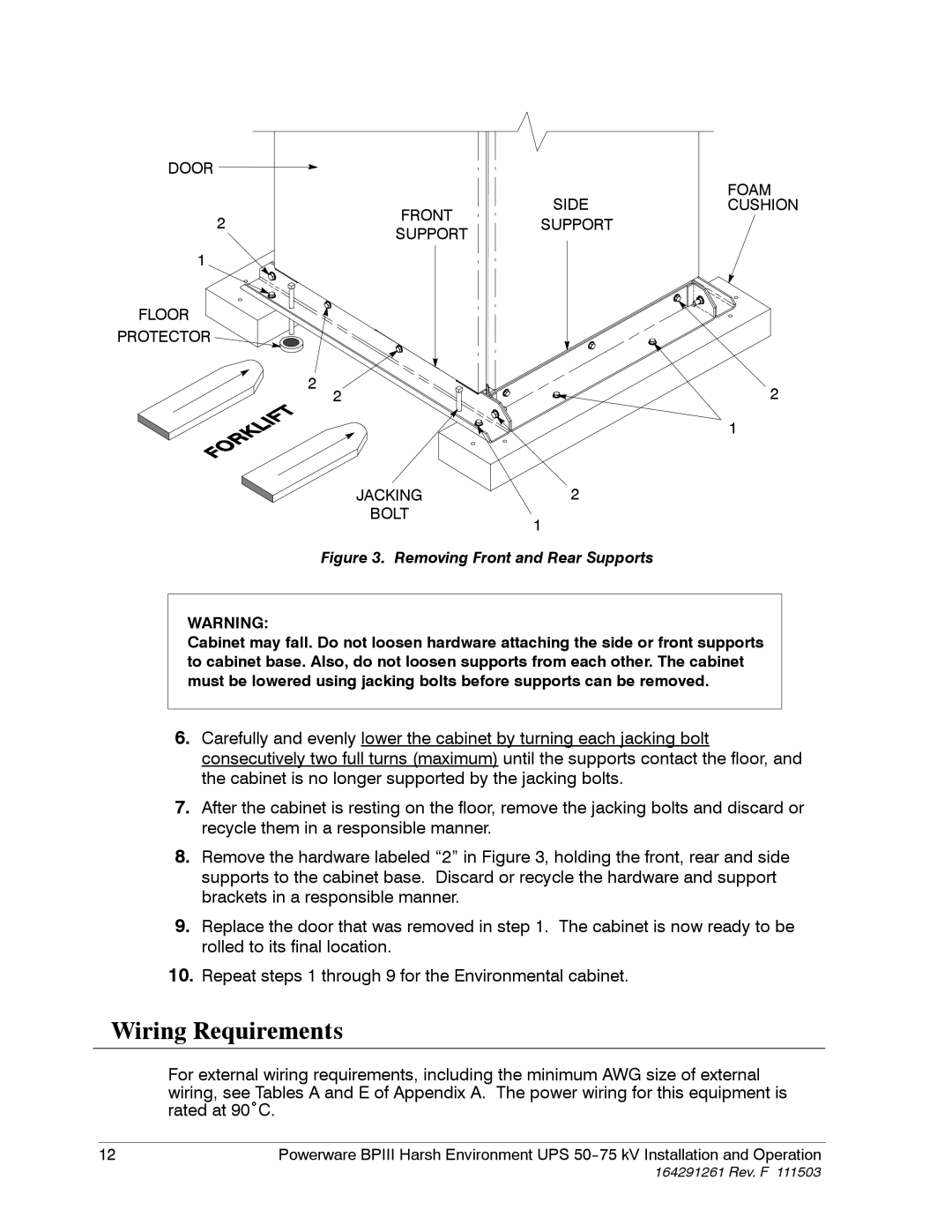
Figure 3. Removing Front and Rear Supports
WARNING:
Cabinet may fall. Do not loosen hardware attaching the side or front supports to cabinet base. Also, do not loosen supports from each other. The cabinet must be lowered using jacking bolts before supports can be removed.
6.Carefully and evenly lower the cabinet by turning each jacking bolt consecutively two full turns (maximum) until the supports contact the floor, and the cabinet is no longer supported by the jacking bolts.
7.After the cabinet is resting on the floor, remove the jacking bolts and discard or recycle them in a responsible manner.
8.Remove the hardware labeled “2” in Figure 3, holding the front, rear and side supports to the cabinet base. Discard or recycle the hardware and support brackets in a responsible manner.
9.Replace the door that was removed in step 1. The cabinet is now ready to be rolled to its final location.
10.Repeat steps 1 through 9 for the Environmental cabinet.
Wiring Requirements
For external wiring requirements, including the minimum AWG size of external wiring, see Tables A and E of Appendix A. The power wiring for this equipment is rated at 90˚C.
12 | Powerware BPIII Harsh Environment UPS |
164291261 Rev. F 111503