16.Battery voltage is computed at 2 volts per cell as defined by Article 480 of the NEC. Rated battery current is computed at 1.8 volts per cell.
17.The battery wiring used between the battery and the UPS should not allow a voltage drop of more than 1% of nominal DC voltage at rated battery current.
18.A battery disconnect switch is recommended, and may be required by NEC or local codes when batteries are remotely located. The battery disconnect switch may be supplied as an accessory, and should be installed between the battery and the UPS.
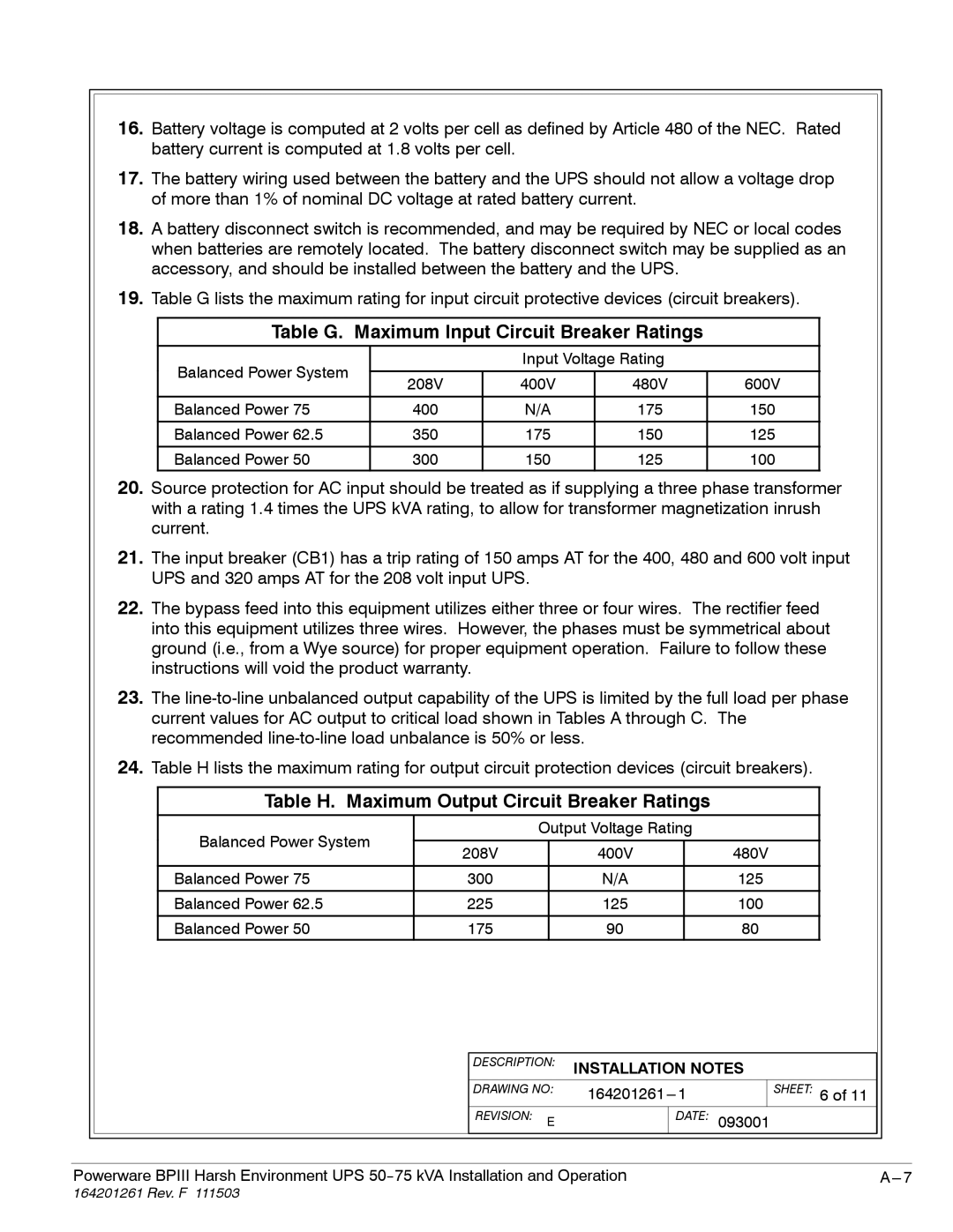
19.Table G lists the maximum rating for input circuit protective devices (circuit breakers).
Table G. Maximum Input Circuit Breaker Ratings
Balanced Power System |
| Input Voltage Rating |
| ||
|
|
|
| ||
208V | 400V | 480V | 600V | ||
| |||||
|
|
|
|
| |
Balanced Power 75 | 400 | N/A | 175 | 150 | |
|
|
|
|
| |
Balanced Power 62.5 | 350 | 175 | 150 | 125 | |
|
|
|
|
| |
Balanced Power 50 | 300 | 150 | 125 | 100 | |
20.Source protection for AC input should be treated as if supplying a three phase transformer with a rating 1.4 times the UPS kVA rating, to allow for transformer magnetization inrush current.
21.The input breaker (CB1) has a trip rating of 150 amps AT for the 400, 480 and 600 volt input UPS and 320 amps AT for the 208 volt input UPS.
22.The bypass feed into this equipment utilizes either three or four wires. The rectifier feed into this equipment utilizes three wires. However, the phases must be symmetrical about ground (i.e., from a Wye source) for proper equipment operation. Failure to follow these instructions will void the product warranty.
23.The
24.Table H lists the maximum rating for output circuit protection devices (circuit breakers).
Table H. Maximum Output Circuit Breaker Ratings
Balanced Power System |
| Output Voltage Rating |
| ||
|
|
|
|
| |
208V |
| 400V |
| 480V | |
|
|
| |||
|
|
|
|
|
|
Balanced Power 75 | 300 |
| N/A |
| 125 |
|
|
|
|
|
|
Balanced Power 62.5 | 225 |
| 125 |
| 100 |
Balanced Power 50 | 175 |
| 90 |
| 80 |
|
|
| DESCRIPTION: | INSTALLATION NOTES |
|
|
| |||
|
|
| DRAWING NO: |
| SHEET: 6 of 11 |
|
|
| ||
|
|
| REVISION: E |
| DATE: | 093001 |
|
|
| |
|
|
|
|
|
|
|
| |||
|
|
|
|
| ||||||
Powerware BPIII Harsh Environment UPS |
|
|
| |||||||