Installing a Remote EPO Control
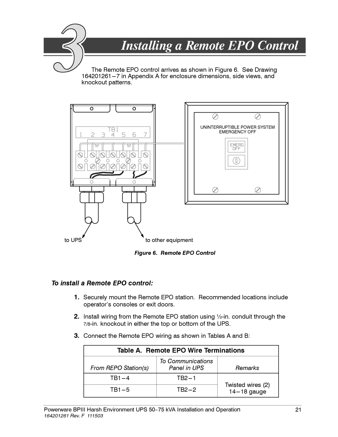
The Remote EPO control arrives as shown in Figure 6. See Drawing
UNINTERRUPTIBLE POWER SYSTEM
EMERGENCY OFF
to UPS | to other equipment |
Figure 6. Remote EPO Control
To install a Remote EPO control:
1.Securely mount the Remote EPO station. Recommended locations include operator’s consoles or exit doors.
2.Install wiring from the Remote EPO station using
3.Connect the Remote EPO wiring as shown in Tables A and B:
| Table A. Remote EPO Wire Terminations |
| ||
|
|
|
|
|
|
| To Communications |
|
|
| From REPO Station(s) | Panel in UPS | Remarks |
|
| Twisted wires (2) |
| ||
|
|
|
| |
|
| |||
|
| |||
|
|
|
|
|
|
|
|
|
|
Powerware BPIII Harsh Environment UPS | 21 | |||
164201261 Rev. F 111503