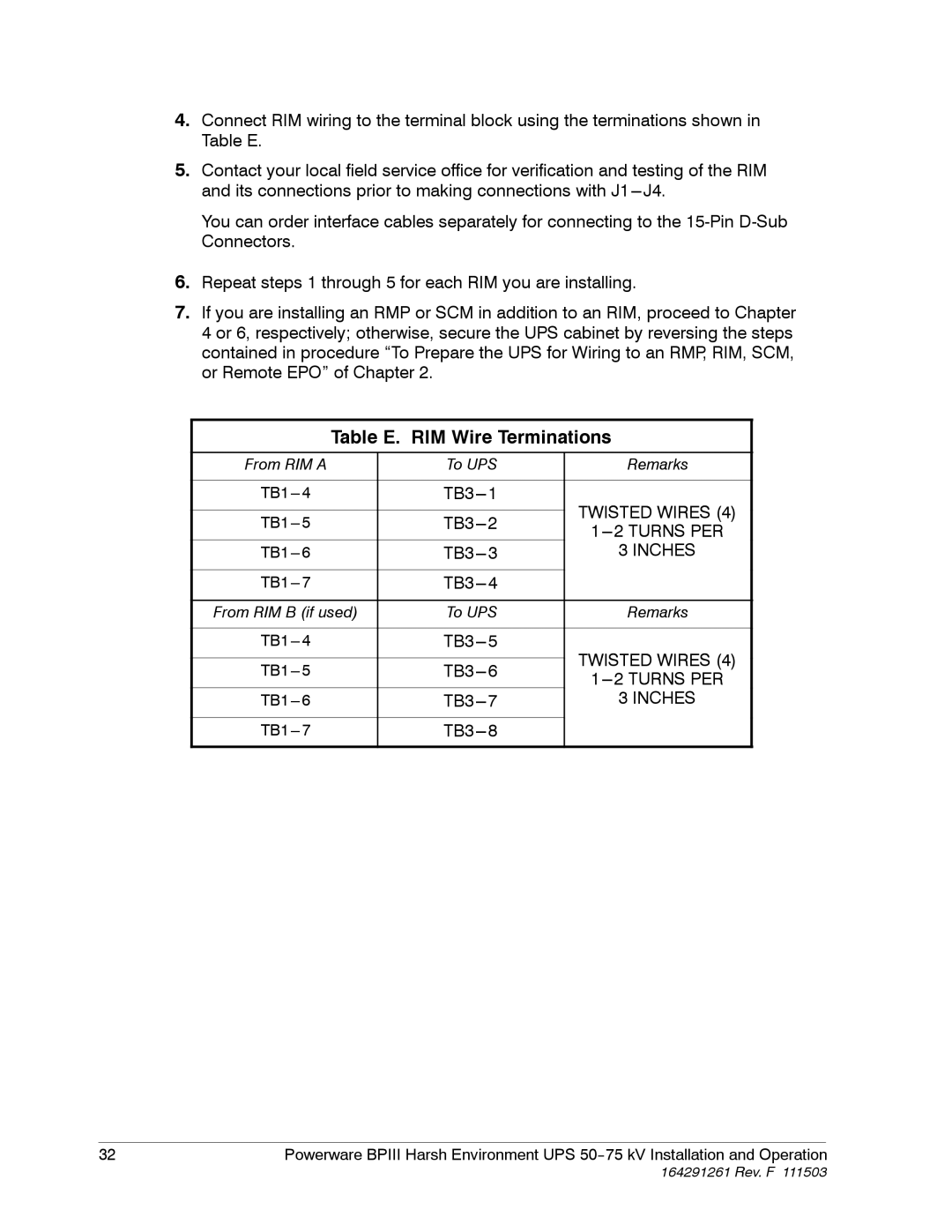
4.Connect RIM wiring to the terminal block using the terminations shown in Table E.
5.Contact your local field service office for verification and testing of the RIM and its connections prior to making connections with
You can order interface cables separately for connecting to the
6.Repeat steps 1 through 5 for each RIM you are installing.
7.If you are installing an RMP or SCM in addition to an RIM, proceed to Chapter 4 or 6, respectively; otherwise, secure the UPS cabinet by reversing the steps contained in procedure “To Prepare the UPS for Wiring to an RMP, RIM, SCM, or Remote EPO” of Chapter 2.
Table E. RIM Wire Terminations
From RIM A | To UPS | Remarks | |
|
|
| |
TWISTED WIRES (4) | |||
|
| ||
|
| ||
3 INCHES | |||
|
|
| |
| |||
|
|
| |
From RIM B (if used) | To UPS | Remarks | |
|
|
| |
TWISTED WIRES (4) | |||
|
| ||
|
| ||
3 INCHES | |||
|
|
| |
|
| ||
|
|
|
32 | Powerware BPIII Harsh Environment UPS |