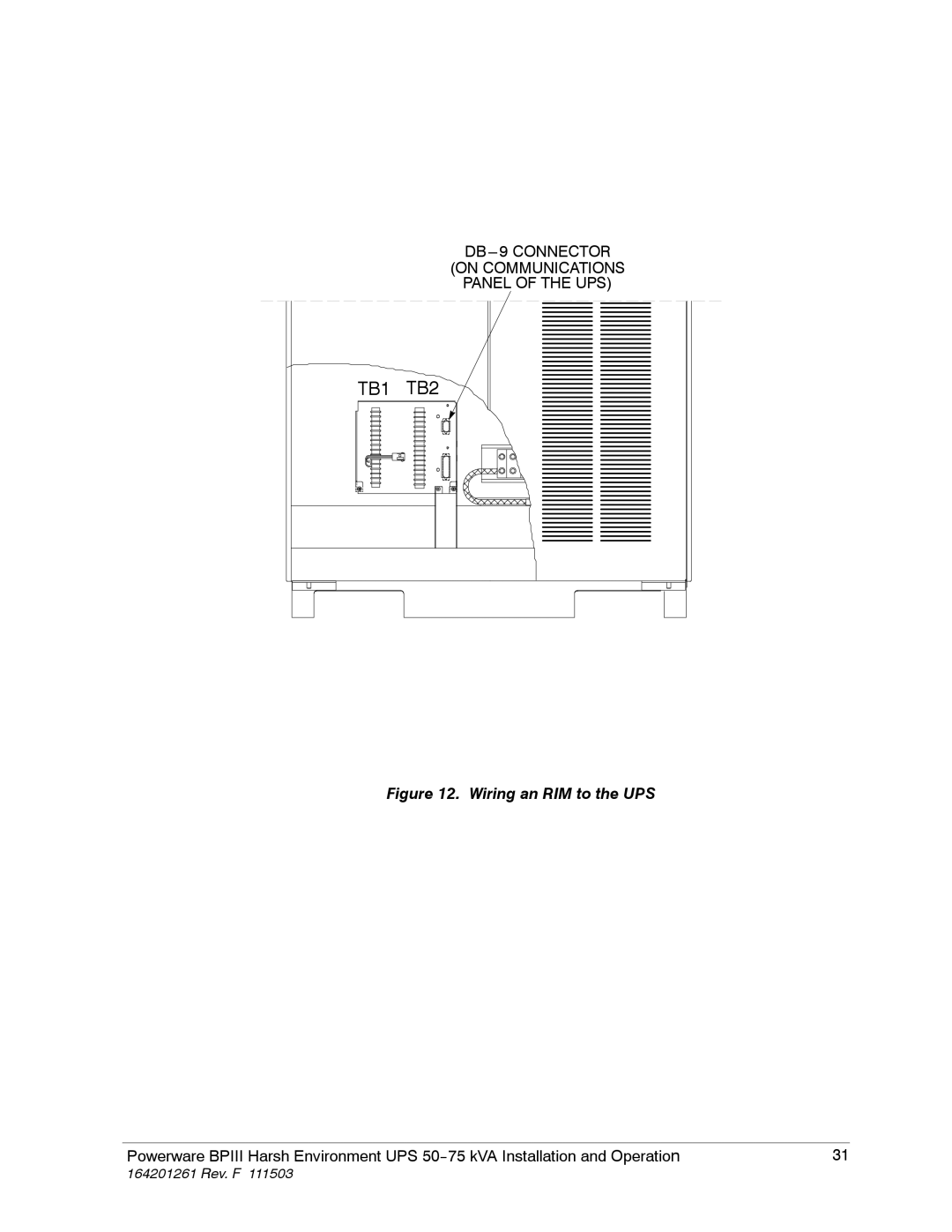
Manuals
/
Brands
/
Computer Equipment
/
Power Supply
/
Powerware
/
Computer Equipment
/
Power Supply
Powerware
5075 kVA
- page 39
1
39
162
162
Download
162 pages, 2.49 Mb
31
Powerware BPIII Harsh Environment UPS 50--75 kVA Installation and Operatio
n
164201261Rev. F
111503
(ON COMMUNICATIONS
PANE L OF THE UP S)
DB
---9
CONN E C T O R
TB1
TB2
Figure12.
Wiring an RIM to the UPS
Contents
Main
Page
Table of Contents
1
2
3 4 5 6
Section II Operation 37
7
8
9
10
11
12
13
14
15
Appendix A A-- -1
16
List of Figures
Page
Introduction
Page
Using This Manual
Conventions Used in This Manual
Safety Considerations
Getting Help
Page
Page
Page
Getting Started
1. 1. 2. 3. 4. 5.
Creating an Installation Plan
Preparing YourSite
Environment Considerations
Inspecting and Unpacking Each Cabinet
1.
2.
3.
Unloading the UPS System From the Pallet
1.
2.
3.
4.
Wiring Requirements
Page
Installing the UPS Cabinet Sections
1.
2.
3.
4.
Grounding Joined Cabinets
1.
2.
Installing UPS Internal Power and Control Wiring
Installing UPS External Wiring
Preparing the UPS for Installing Optional Accessories
Initial Startup
Completing the Installation Checklist
Page
Page
Installing a Remote EPO Control
Toinstall a Remote EPO control: 1.
2.
3. TableA. RemoteEPOWireTerminations
TB2
Installing a Remote Monitor Panel
TableC. Optional Monitoring Accessories
Page
To ins t a l l an RM P : 1. 2.
3.
TB1 TB2
4. Tab l e D. R M P Wi r e Ter m i n a t i o n s
5.
6.
7. 8.
Page
Installing a Relay Interface Module
To ins t a l l an RI M : 1. 2.
3.
Page
4.
5.
6. 7.
Tab l e E. RI M Wir e Ter m i n a t i o n s
Installing a Supervisory Contact Module
Toinstall a Supervisory Contact Module: 1. 2.
3.
TB1 TB2
4.
5.
6. 7.
TableF. Supervisory Contact Module Wire Terminations
Page
Page
Page
Understanding UPS Operation
Looking Inside the UPS
Normal Mode
Bypass Mode
Battery Mode
Maintenance Bypass Mode
Monitoring and Controlling UPS Operation
Page
Controls and Features
UPS Controls
Control Panel
Monitor Panel
Maintenance Bypass
Options and Accessories
Safety Considerations
Symbols, Controls, and Indicators
Using the Monitor Panel
52 Powerware BPIII Harsh Environment UPS 50--75 kV Installation and Operation
164291261Rev. F 111503
The Monitor Panelcontains:
1. 2. 3. 4.
A
B
C
D
E
Using the Pushbuttons
Adjusting the Contrast
Reading the Status Indicators
Normal
Battery
Bypass
Notice
Using the Menu Options
56 Powerware BPIII Harsh Environment UPS 50--75 kV Installation and Operation
164291261Rev. F 111503
Figure26. Load Amps Meters Screen
Page
Page
59
Figure 29. Unit Statistics Screen
Page
Page
Page
Operating the UPS
Using the Operating Controls
S
Operation
ToPlace the UPS in N ormal Mode:
ToShut Down the UPS from Normal Mode:
ToStart the UPS in Bypass Mode:
ToTransfer the Critical Load to Maintenance Bypass from UPS Bypass:
ToTransfer the Critical Load to UPS Bypass from Maintenance Bypass:
ToCold Start the UPS from Battery (No AC Input Power):
ToShut Down the UPS from Cold Start:
ToReset the DC to DC Converter:
Using the EMERGENCY POWER OFF Pushbutton
ToU se the EMERGENCY POWER OFF Pushbutton
1.
2.
Resetting UPS System after Emergency Power Off
Using Features and Options
RS232
Building Alarm Monitoring
TB1
RS485
Summary Alarm Contacts
Remote Monitor Panel
Table1. Optional Monitoring Accessories
The RMP contains a local horn and the following backlit status indicators:
Relay Interface Module
Supervisory Contact Module
Responding to System Events
System Event Horns
System Event Lights
System Event Messages
Page
Page
Page
Page
Page
Page
Serial Communications
Locating the Communications Panel
Connecting Equipment to a Serial Port
PORT 1 (DB--9)
Table 2. Pin Assignments for Port 1 (DB---9)
PORT 2 (DB--25)Optional
Table 3. Pin Assignments for Port 2 (DB---25)
Pin # Symbol Description Comments
3
5
Configuring the Serial Ports
Tab l e 4.
Mode
Rate
Data/Stop
Handshaking
Disabled (No Handshaking)
XON/XOFF
Save
Ter mi na l Mo de
Printing Selected Information
Entire Log (Ctrl + P)
Meters Printout (Ctrl + M)
+
System Information Printout (Ctrl + A)
Battery TestPrintout (Ctrl + B)
System Configuration
System Configuration Mode Main Menu
Program Building Alarms
Enable/Disable Default Functions
Customize Alarm Messages
ProgramUnit Name
Adjust Output Voltage
Change Password
Battery TestSetup
Modify Low Battery Time
Calibration Mode
Computer Mode
Remote Monitor Mode
Page
Optional Remote Notification
Remote Notification Features
Description of Operation
Housekeeping
Hardware Requirements
Configuring the Modem
Basic Modem Configuration
Configuring the Modem to Call a Remote Computer
Configuring the Modem to Call a Numeric Pager
Configuring the Modem to Answer Incoming Calls
Final Modem Configuration
UPS Setup Configuration
User-Selected Events
Page
Page
Page
Maintaining the UPS System
Important Safety Instructions
Performing Preventive Maintenance
1. 2. 3. 4.
Maintenance Training
Page
Product Specifications
System Input
System Output
Environmental Specifications
Battery Specifications
Page
Appendix A --- Customer Information
map to drawing #164201261---3
,,,
A--- 2 Powerware BPIII Harsh Environment UPS 50--75 kV Installation and Operation
Tab l e A. INPUTRatings & External Wiring Requirem ents for
Powerware BPIII HE 50---75 kVA (208, 480, and 600 Volt)
KVA KW
40
62.5
75 60
Powerware BPIII HE 50---75 kVA (208 and 480 Volt)
7.
accommodate double-sized neutral terminations if needed.
8.
9.
PowerwareBPIII HE 50 and 62.5 kVA (400 Volt)
50 Hz
KVA KW
40
62.5
10.
TableD. Internal Power Cable Terminations
TableE. External Power Cable Terminations
11.
Required for cooling air exhaust: approximately 614.0 liters/sec (1300 cfm).
are bolted togetheron site.
12. 13. 14. TableF. Air Conditioning or Ventilation Requirements DuringFull Load Operation
16.
17.
18.
19. TableG. Maximum Input Circuit Breaker Ratings
20.
25. TableI. Maximum DC Input Circuit Breaker Ratings
26.
27.
TB1
RS232
Communications Panel
(Optional)
NOTE:
use an isolated normallyopen contactor switch (24VDC, 20ma minimum) connected at TB2-1 and TB2-2.
TableK. Communications PanelInputs and Outputs
28.
RELAY2
RELAY1
g
29.
TB2
TableN. RemoteEPO
1 2
Page
UPS SYSTEM WITH 480/480 OR 400/400 VOLT INPUT/OUTPUT
UPS SYSTEM WITH 480/208 VOLT INPUT/OUTPUT
UPS SYSTEM WITH 208/208 VOLT INPUT/OUTPUT
UPS SYSTEM WITH 600/208 VOLT INPUT/OUTPUT
NOTE:
INTERCABINET WIRING
NOTE:
Page
Page
Page
Page
Page
Page
Page
W--1
Powerware BPIII Harsh Environment UPS 50--75 kVA Installation and Operation
LIMITED FACTORYWARRANTY FOR THREE-PHASE POWERWARE PRODUCTS