Normal Mode
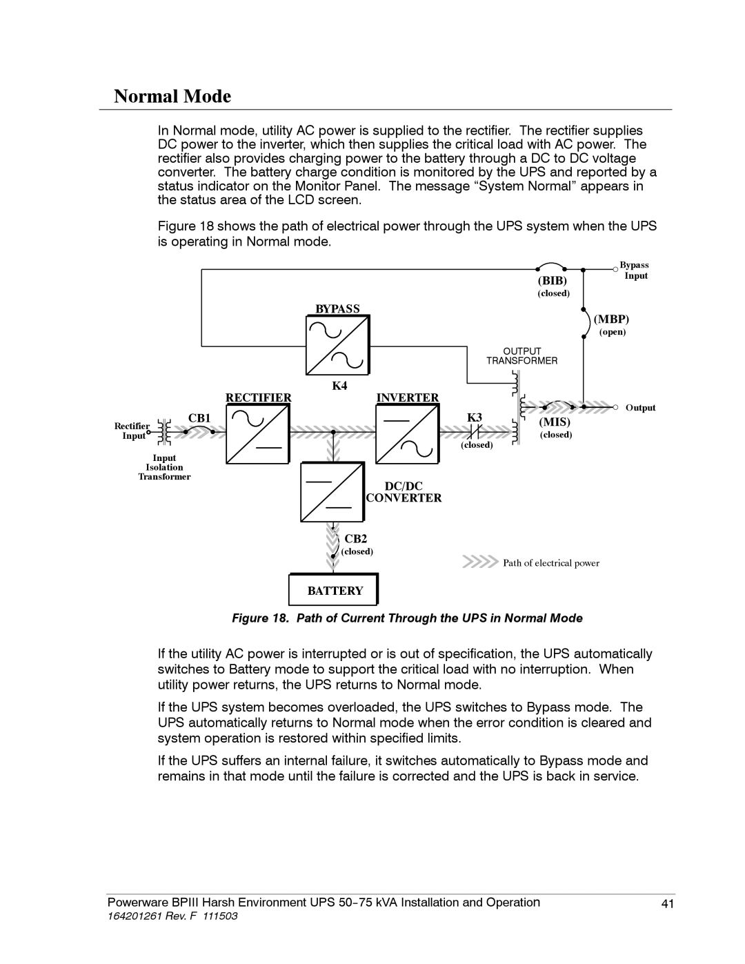
In Normal mode, utility AC power is supplied to the rectifier. The rectifier supplies DC power to the inverter, which then supplies the critical load with AC power. The rectifier also provides charging power to the battery through a DC to DC voltage converter. The battery charge condition is monitored by the UPS and reported by a status indicator on the Monitor Panel. The message “System Normal” appears in the status area of the LCD screen.
Figure 18 shows the path of electrical power through the UPS system when the UPS is operating in Normal mode.
|
|
|
|
| Bypass |
|
|
|
| (BIB) | Input |
|
|
|
|
| |
|
|
|
| (closed) |
|
|
| BYPASS |
|
| (MBP) |
|
|
|
|
| |
|
|
|
|
| (open) |
|
|
|
| OUTPUT |
|
|
|
|
| TRANSFORMER |
|
| RECTIFIER | K4 | INVERTER |
|
|
|
|
| Output | ||
| CB1 |
| K3 |
| |
Rectifier |
| (MIS) |
| ||
|
|
|
| ||
Input |
|
|
| (closed) |
|
|
|
| (closed) |
| |
Input
Isolation
Transformer
DC/DC
CONVERTER
CB2
(closed)
BATTERY
![]()
![]() Path of electrical power
Path of electrical power
Figure 18. Path of Current Through the UPS in Normal Mode
If the utility AC power is interrupted or is out of specification, the UPS automatically switches to Battery mode to support the critical load with no interruption. When utility power returns, the UPS returns to Normal mode.
If the UPS system becomes overloaded, the UPS switches to Bypass mode. The UPS automatically returns to Normal mode when the error condition is cleared and system operation is restored within specified limits.
If the UPS suffers an internal failure, it switches automatically to Bypass mode and remains in that mode until the failure is corrected and the UPS is back in service.
Powerware BPIII Harsh Environment UPS | 41 |
