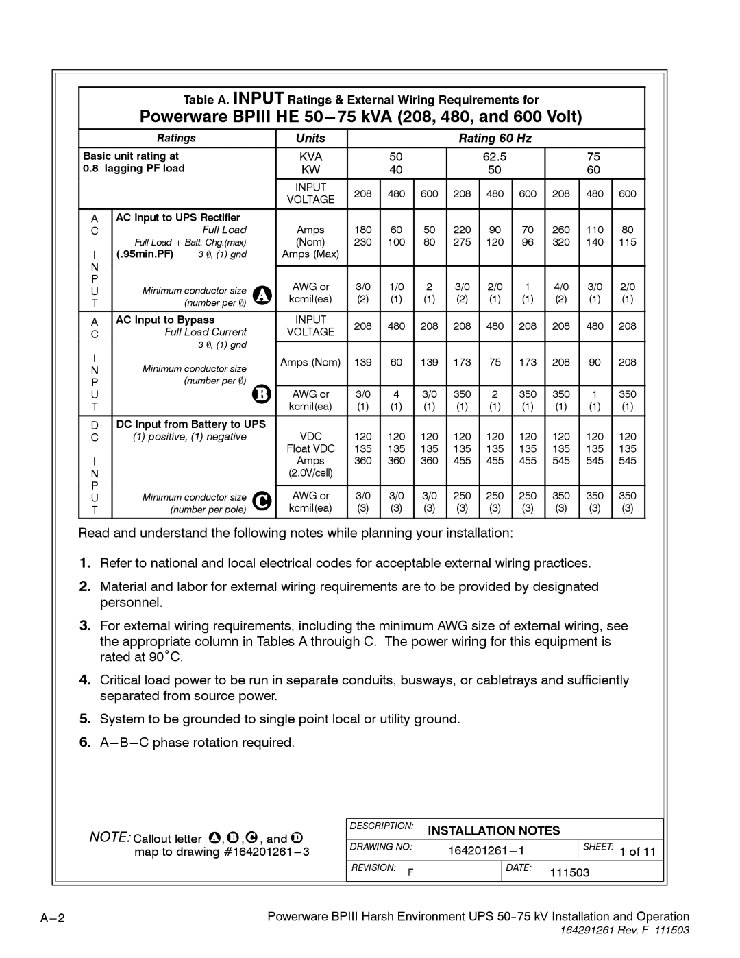
Table A. INPUT Ratings & External Wiring Requirements for
Powerware BPIII HE 50---75 kVA (208, 480, and 600 Volt)
|
| Ratings | Units |
|
|
| Rating 60 Hz |
|
|
| |||
Basic unit rating at |
| KVA |
| 50 |
|
| 62.5 |
|
| 75 |
| ||
0.8 | lagging PF load | KW |
| 40 |
|
| 50 |
|
| 60 |
| ||
|
|
|
| INPUT | 208 | 480 | 600 | 208 | 480 | 600 | 208 | 480 | 600 |
|
|
|
| VOLTAGE | |||||||||
|
|
|
|
|
|
|
|
|
|
|
|
| |
|
|
|
|
|
|
|
|
|
|
|
|
| |
A |
| AC Input to UPS Rectifier |
|
|
|
|
|
|
|
|
|
| |
C |
|
| Full Load | Amps | 180 | 60 | 50 | 220 | 90 | 70 | 260 | 110 | 80 |
|
| Full Load + Batt. Chg.(max) | (Nom) | 230 | 100 | 80 | 275 | 120 | 96 | 320 | 140 | 115 | |
I |
| (.95min.PF) | 3 , (1) gnd | Amps (Max) |
|
|
|
|
|
|
|
|
|
N |
|
|
|
|
|
|
|
|
|
|
|
|
|
|
|
|
|
|
|
|
|
|
|
|
|
| |
P |
| Minimum conductor size | AWG or | 3/0 | 1/0 | 2 | 3/0 | 2/0 | 1 | 4/0 | 3/0 | 2/0 | |
U |
| ||||||||||||
| kcmil(ea) | (2) | (1) | (1) | (2) | (1) | (1) | (2) | (1) | (1) | |||
T |
|
| (number per ) | ||||||||||
|
|
|
|
|
|
|
|
|
|
|
| ||
A |
| AC Input to Bypass | INPUT | 208 | 480 | 208 | 208 | 480 | 208 | 208 | 480 | 208 | |
C |
| Full Load Current | VOLTAGE | ||||||||||
|
|
|
|
|
|
|
|
|
| ||||
I |
|
| 3 , (1) gnd |
|
|
|
|
|
|
|
|
|
|
|
| Amps (Nom) | 139 | 60 | 139 | 173 | 75 | 173 | 208 | 90 | 208 | ||
| Minimum conductor size | ||||||||||||
N |
| ||||||||||||
|
|
|
|
|
|
|
|
|
|
| |||
P |
|
| (number per ) |
|
|
|
|
|
|
|
|
|
|
U |
|
|
| AWG or | 3/0 | 4 | 3/0 | 350 | 2 | 350 | 350 | 1 | 350 |
T |
|
|
| kcmil(ea) | (1) | (1) | (1) | (1) | (1) | (1) | (1) | (1) | (1) |
|
|
|
|
|
|
|
|
|
|
|
|
| |
D |
| DC Input from Battery to UPS |
|
|
|
|
|
|
|
|
|
| |
C |
| (1) positive, (1) negative | VDC | 120 | 120 | 120 | 120 | 120 | 120 | 120 | 120 | 120 | |
|
|
|
| Float VDC | 135 | 135 | 135 | 135 | 135 | 135 | 135 | 135 | 135 |
I |
|
|
| Amps | 360 | 360 | 360 | 455 | 455 | 455 | 545 | 545 | 545 |
N |
|
|
| (2.0V/cell) |
|
|
|
|
|
|
|
|
|
P |
|
|
|
|
|
|
|
|
|
|
|
|
|
| Minimum conductor size | AWG or | 3/0 | 3/0 | 3/0 | 250 | 250 | 250 | 350 | 350 | 350 | ||
U |
| ||||||||||||
T |
| (number per pole) | kcmil(ea) | (3) | (3) | (3) | (3) | (3) | (3) | (3) | (3) | (3) | |
Read and understand the following notes while planning your installation:
1.Refer to national and local electrical codes for acceptable external wiring practices.
2.Material and labor for external wiring requirements are to be provided by designated personnel.
3.For external wiring requirements, including the minimum AWG size of external wiring, see the appropriate column in Tables A throuigh C. The power wiring for this equipment is rated at 90˚C.
4.Critical load power to be run in separate conduits, busways, or cabletrays and sufficiently separated from source power.
5.System to be grounded to single point local or utility ground.
6.
NOTE: Callout letter ![]() ,
, ![]() ,
,![]() , and
, and ![]() map to drawing
map to drawing
DESCRIPTION: | INSTALLATION NOTES | ||||
DRAWING NO: |
| SHEET: 1 of 11 | |||
REVISION: | F |
| DATE: | 111503 | |
|
|
| |||
Powerware BPIII Harsh Environment UPS |