28.Use Class 1 wiring methods (as defined by the NEC) for control wiring. Install the control wiring in separate ferrous conduit from the power wiring. The wire should be rated at 24 volts, 1 amp minimum. Control wiring and conduit to be supplied by designated personnel.
29.Refer to Tables L, M, and N, and to applicable chapters for information about installing control wiring for options and accessories.
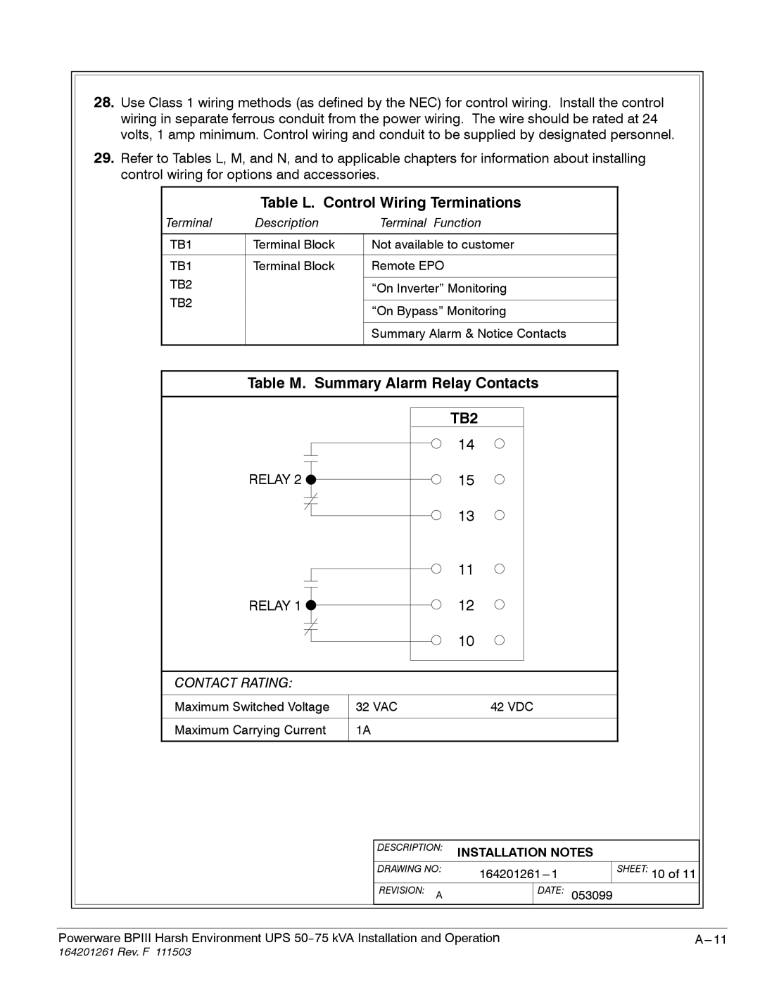
Table L. Control Wiring Terminations
Terminal | Description | Terminal Function |
|
|
|
TB1 | Terminal Block | Not available to customer |
|
|
|
TB1 | Terminal Block | Remote EPO |
TB2 |
|
|
| “On Inverter” Monitoring | |
TB2 |
|
|
| “On Bypass” Monitoring | |
|
| |
|
|
|
|
| Summary Alarm & Notice Contacts |
|
|
|
Table M. Summary Alarm Relay Contacts
| TB2 |
| 14 |
RELAY 2 | 15 |
| 13 |
| 11 |
RELAY 1 | 12 |
| 10 |
CONTACT RATING:
Maximum Switched Voltage | 32 VAC | 42 VDC |
|
|
|
Maximum Carrying Current | 1A |
|
|
|
|
|
|
| DESCRIPTION: | INSTALLATION NOTES |
|
|
| |||
|
|
| DRAWING NO: |
| SHEET: 10 of 11 |
|
|
| ||
|
|
| REVISION: A |
| DATE: | 053099 |
|
|
| |
|
|
|
|
|
| |||||
|
|
| ||||||||
Powerware BPIII Harsh Environment UPS |
| |||||||||