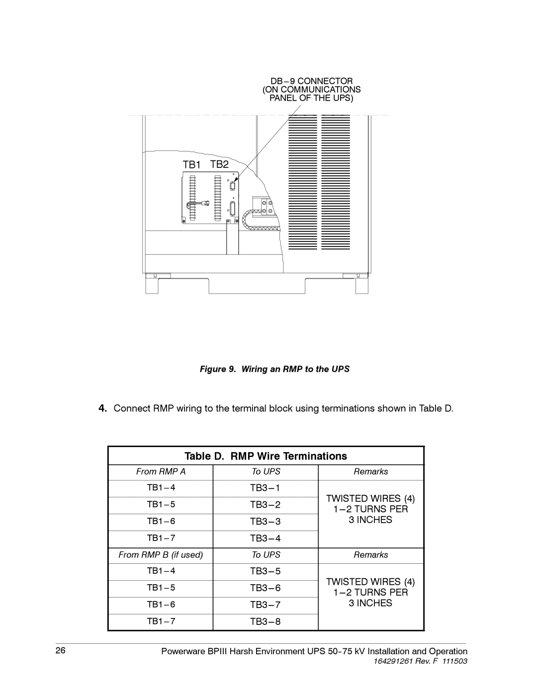
(ON COMMUNICATIONS
PANEL OF THE UPS)
TB1 TB2
Figure 9. Wiring an RMP to the UPS
4.Connect RMP wiring to the terminal block using terminations shown in Table D.
| Table D. RMP Wire Terminations |
| |||
|
|
|
|
| |
| From RMP A | To UPS | Remarks |
|
|
|
|
|
|
|
|
| TWISTED WIRES (4) |
|
| ||
|
|
|
| ||
|
|
| |||
|
|
| |||
|
|
|
| ||
| 3 INCHES |
|
| ||
|
|
|
|
|
|
|
|
|
| ||
|
|
|
|
| |
| From RMP B (if used) | To UPS | Remarks |
|
|
|
|
|
|
|
|
| TWISTED WIRES (4) |
|
| ||
|
|
|
| ||
|
|
| |||
|
|
| |||
|
|
|
| ||
| 3 INCHES |
|
| ||
|
|
|
|
|
|
|
|
|
| ||
|
|
|
|
| |
|
|
|
|
|
|
26 | Powerware BPIII Harsh Environment UPS | ||||