Using the Operating Controls
Although the operating controls appear easy to use, you should read these instructions and thoroughly understand how the controls work before attempting to use them. Refer to oneline drawing
CAUTION:
Incorrect use of the power controls can cause a loss of power to your critical load.
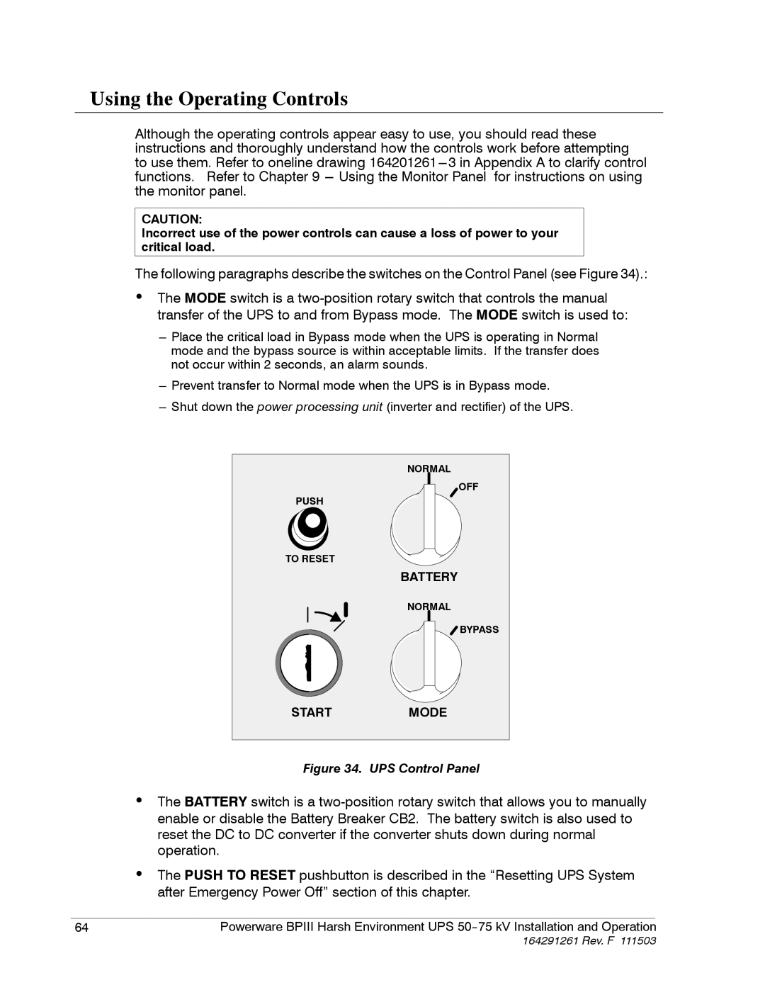
The following paragraphs describe the switches on the Control Panel (see Figure 34).:
•The MODE switch is a
---Place the critical load in Bypass mode when the UPS is operating in Normal mode and the bypass source is within acceptable limits. If the transfer does not occur within 2 seconds, an alarm sounds.
---Prevent transfer to Normal mode when the UPS is in Bypass mode.
---Shut down the power processing unit (inverter and rectifier) of the UPS.
| NORMAL |
| OFF |
PUSH |
|
TO RESET |
|
| BATTERY |
| NORMAL |
| BYPASS |
START | MODE |
Figure 34. UPS Control Panel
•The BATTERY switch is a
•The PUSH TO RESET pushbutton is described in the “Resetting UPS System after Emergency Power Off” section of this chapter.
|
|
|
64 | Powerware BPIII Harsh Environment UPS | |
