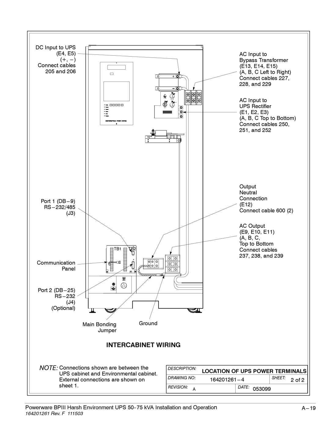
DC Input to UPS (E4, E5)
(+,
Port 1
TB1 ![]() TB2
TB2
Communication ![]()
![]()
Panel
Port 2
Main Bonding | Ground |
Jumper |
|
INTERCABINET WIRING
AC Input to
Bypass Transformer (E13, E14, E15)
(A, B, C Left to Right) Connect cables 227, 228, and 229
AC Input to UPS Rectifier (E1, E2, E3)
(A, B, C Top to Bottom) Connect cables 250, 251, and 252
Output
Neutral Connection (E12)
Connect cable 600 (2)
AC Output (E9, E10, E11) (A, B, C, Top to Bottom Connect cables 237, 238, and 239
NOTE: Connections shown are between the UPS cabinet and Environmental cabinet. External connections are shown on sheet 1.
DESCRIPTION: LOCATION OF UPS POWER TERMINALS
DRAWING NO: |
| SHEET: 2 of 2 | ||
REVISION: A |
| DATE: | 053099 | |
Powerware BPIII Harsh Environment UPS |