8Insert the two screws included with the interface card package into the appropriate holes above and below the Ethernet network port, as shown below. Carefully tighten them.
9Insert the antenna counter clockwise and flip it upright, as shown.
10Replace the metal cover, as shown below, and replace the four screws you removed in step 4.
11Replace the control board cover, as shown below, and replace the four screws you removed in step 2.
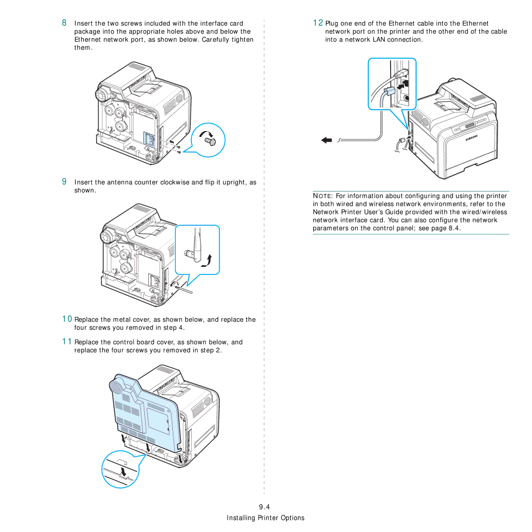
12Plug one end of the Ethernet cable into the Ethernet network port on the printer and the other end of the cable into a network LAN connection.
NOTE: For information about configuring and using the printer in both wired and wireless network environments, refer to the Network Printer User’s Guide provided with the wired/wireless network interface card. You can also configure the network parameters on the control panel; see page 8.4.
9.4