PowerLogic™ PM5300 series user guideChapter
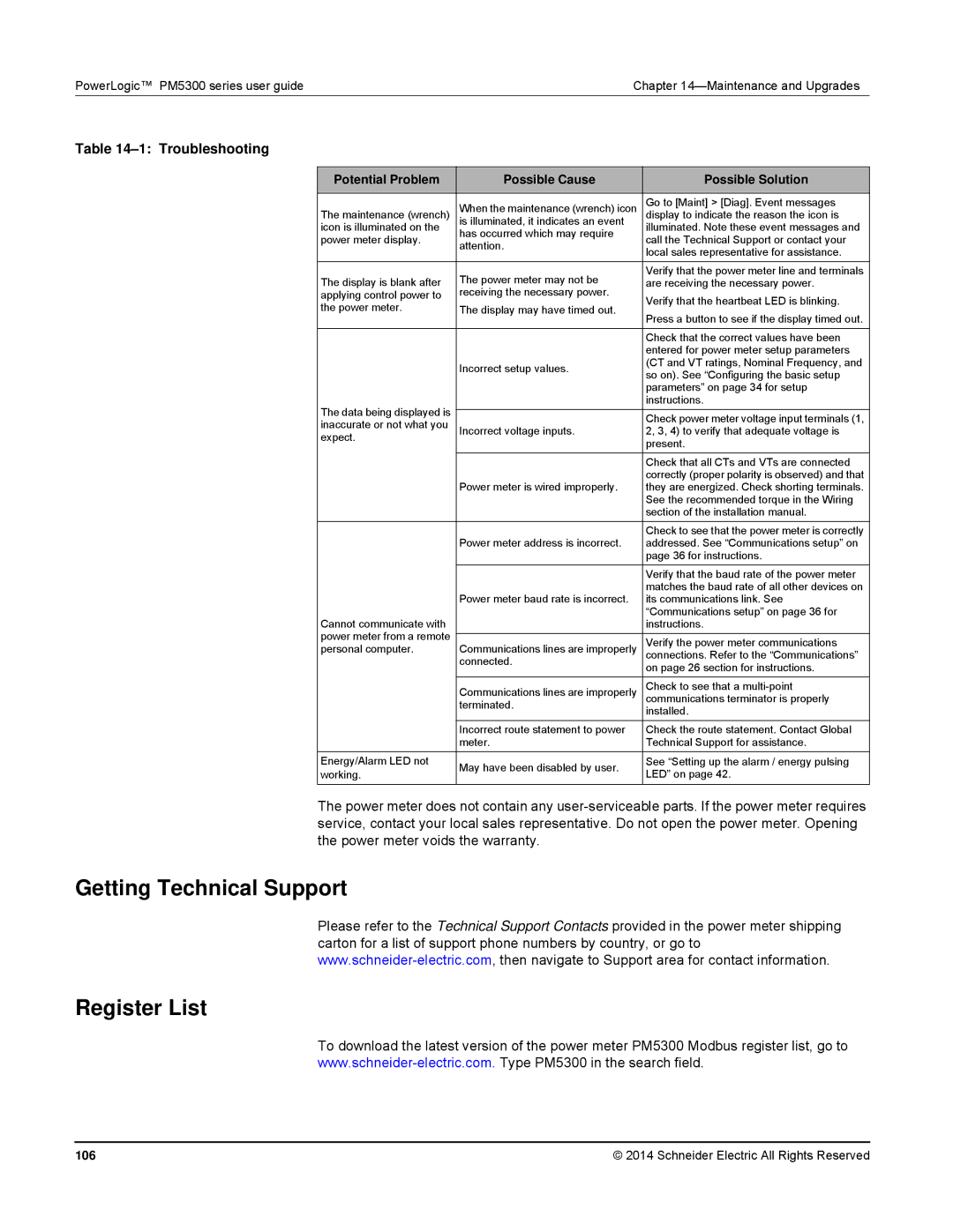
Table 14–1: Troubleshooting
Potential Problem | Possible Cause | Possible Solution | |
| When the maintenance (wrench) icon | Go to [Maint] > [Diag]. Event messages | |
The maintenance (wrench) | display to indicate the reason the icon is | ||
icon is illuminated on the | is illuminated, it indicates an event | illuminated. Note these event messages and | |
has occurred which may require | |||
power meter display. | call the Technical Support or contact your | ||
attention. | |||
| local sales representative for assistance. | ||
|
| ||
|
|
| |
The display is blank after | The power meter may not be | Verify that the power meter line and terminals | |
are receiving the necessary power. | |||
applying control power to | receiving the necessary power. | Verify that the heartbeat LED is blinking. | |
the power meter. | The display may have timed out. | ||
Press a button to see if the display timed out. | |||
|
| ||
|
|
| |
|
| Check that the correct values have been | |
|
| entered for power meter setup parameters | |
| Incorrect setup values. | (CT and VT ratings, Nominal Frequency, and | |
| so on). See “Configuring the basic setup | ||
|
| ||
|
| parameters” on page 34 for setup | |
The data being displayed is |
| instructions. | |
| Check power meter voltage input terminals (1, | ||
inaccurate or not what you |
| ||
Incorrect voltage inputs. | 2, 3, 4) to verify that adequate voltage is | ||
expect. |
| present. | |
|
| ||
|
|
| |
|
| Check that all CTs and VTs are connected | |
| Power meter is wired improperly. | correctly (proper polarity is observed) and that | |
| they are energized. Check shorting terminals. | ||
|
| See the recommended torque in the Wiring | |
|
| section of the installation manual. | |
|
| Check to see that the power meter is correctly | |
| Power meter address is incorrect. | addressed. See “Communications setup” on | |
|
| page 36 for instructions. | |
|
| Verify that the baud rate of the power meter | |
| Power meter baud rate is incorrect. | matches the baud rate of all other devices on | |
| its communications link. See | ||
Cannot communicate with |
| “Communications setup” on page 36 for | |
| instructions. | ||
power meter from a remote |
|
| |
| Verify the power meter communications | ||
personal computer. | Communications lines are improperly | ||
connections. Refer to the “Communications” | |||
| connected. | on page 26 section for instructions. | |
|
| ||
|
|
| |
| Communications lines are improperly | Check to see that a | |
| terminated. | communications terminator is properly | |
| installed. | ||
|
| ||
| Incorrect route statement to power | Check the route statement. Contact Global | |
| meter. | Technical Support for assistance. | |
Energy/Alarm LED not | May have been disabled by user. | See “Setting up the alarm / energy pulsing | |
working. | LED” on page 42. | ||
| |||
|
|
|
The power meter does not contain any
Getting Technical Support
Please refer to the Technical Support Contacts provided in the power meter shipping carton for a list of support phone numbers by country, or go to
Register List
To download the latest version of the power meter PM5300 Modbus register list, go to
106 | © 2014 Schneider Electric All Rights Reserved |
