Chapter | PowerLogic™ PM5300 series user guide |
|
|
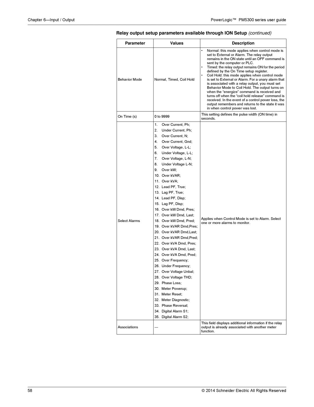
Relay output setup parameters available through ION Setup (continued)
Parameter |
| Values | Description | |
|
|
|
| |
|
|
| • Normal: this mode applies when control mode is | |
|
|
| set to External or Alarm. The relay output | |
|
|
| remains in the ON state until an OFF command is | |
|
|
| sent by the computer or PLC. | |
|
|
| • Timed: the relay output remains ON for the period | |
|
|
| defined by the On Time setup register. | |
Behavior Mode | Normal, Timed, Coil Hold | • Coil Hold: this mode applies when control mode | ||
is set to External or Alarm. For a unary alarm that | ||||
|
|
| is associated with a relay output, you must set | |
|
|
| Behavior Mode to Coil Hold. The output turns on | |
|
|
| when the “energize” command is received and | |
|
|
| turns off when the “coil hold release” command is | |
|
|
| received. In the event of a control power loss, the | |
|
|
| output remembers and returns to the state it was | |
|
|
| in when control power was lost. | |
On Time (s) | 0 to 9999 | This setting defines the pulse width (ON time) in | ||
seconds. | ||||
|
|
| ||
| 1. | Over Current, Ph; |
| |
| 2. | Under Current, Ph; |
| |
| 3. | Over Current, N; |
| |
| 4. | Over Current, Gnd; |
| |
| 5. | Over Voltage, |
| |
| 6. | Under Voltage, |
| |
| 7. | Over Voltage, |
| |
| 8. | Under Voltage |
| |
| 9. | Over kW; |
| |
| 10. | Over kVAR; |
| |
| 11. | Over kVA; |
| |
| 12. | Lead PF, True; |
| |
| 13. | Lag PF, True; |
| |
| 14. | Lead PF, Disp; |
| |
| 15. | Lag PF, Disp; |
| |
| 16. | Over kW Dmd, Pres; |
| |
| 17. | Over kW Dmd, Last; | Applies when Control Mode is set to Alarm. Select | |
Select Alarms | 18. | Over kW Dmd, Pred; | ||
one or more alarms to monitor. | ||||
| 19. | Over kVAR Dmd,Pres; | ||
|
| |||
| 20. | Over kVAR Dmd,Last; |
| |
| 21. | Over kVAR Dmd,Pred; |
| |
| 22. | Over kVA Dmd, Pres; |
| |
| 23. | Over kVA Dmd, Last; |
| |
| 24. | Over kVA Dmd, Pred; |
| |
| 25. | Over Frequency; |
| |
| 26. | Under Frequency; |
| |
| 27. | Over Voltage Unbal; |
| |
| 28. | Over Voltage THD; |
| |
| 29. | Phase Loss; |
| |
| 30. | Meter Powerup; |
| |
| 31. | Meter Reset; |
| |
| 32. | Meter Diagnostic; |
| |
| 33. | Phase Reversal; |
| |
| 34. | Digital Alarm S1; |
| |
| 35. | Digital Alarm S2; |
| |
|
|
|
| |
|
|
| This field displays additional information if the relay | |
Associations | — |
| output is already associated with another meter | |
|
|
| function. | |
58 | © 2014 Schneider Electric All Rights Reserved |