PowerLogic™ PM5300 series user guide | Chapter |
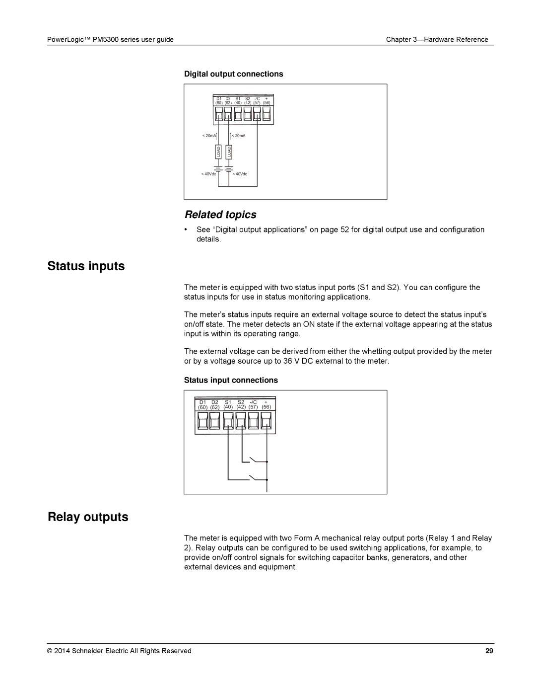
Digital output connections
D1 D2 S1 S2
(60) (62) (40) (42) (57) (56)
< 20mA
LOAD
< 20mA
LOAD
< 40Vdc
< 40Vdc
Related topics
•See “Digital output applications” on page 52 for digital output use and configuration details.
Status inputs
The meter is equipped with two status input ports (S1 and S2). You can configure the status inputs for use in status monitoring applications.
The meter’s status inputs require an external voltage source to detect the status input’s on/off state. The meter detects an ON state if the external voltage appearing at the status input is within its operating range.
The external voltage can be derived from either the whetting output provided by the meter or by a voltage source up to 36 V DC external to the meter.
Status input connections
D1 D2 S1 S2
(60) (62) (40) (42) (57) (56)
Relay outputs
The meter is equipped with two Form A mechanical relay output ports (Relay 1 and Relay 2). Relay outputs can be configured to be used switching applications, for example, to provide on/off control signals for switching capacitor banks, generators, and other external devices and equipment.
© 2014 Schneider Electric All Rights Reserved | 29 |