Chapter | PowerLogic™ PM5300 series user guide |
|
|
Digital output applications
Digital outputs are typically used in switching applications, for example, to provide on/off control signals for switching capacitor banks, generators, and other external devices and equipment. They can also be used in demand synchronization applications, where the meter provides pulse signals to the input of another meter to control its demand period.
The digital output can also be used in energy pulsing applications, where a receiving device determines energy usage by counting the kWh pulses coming from the meter’s digital output port.
![]() DANGER
DANGER
HAZARD OF ELECTRIC SHOCK, EXPLOSION, OR ARC FLASH
•Apply appropriate personal protective equipment (PPE) and follow safe electrical work practices. See NFPA 70E in the USA or applicable local standards.
•Turn off all power supplying this device before working on it.
•Always use a properly rated voltage sensing device to confirm that all power is off.
•Do not exceed the device’s ratings for maximum limits.
•Do not use this device for critical control or protection applications where human or equipment safety relies on the operation of the control circuit.
Failure to follow these instructions will result in death or serious injury.
NOTE: Be aware that an unexpected change of state of the digital outputs may result when the supply power to the meter is interrupted or after a meter firmware upgrade.
Digital output application example
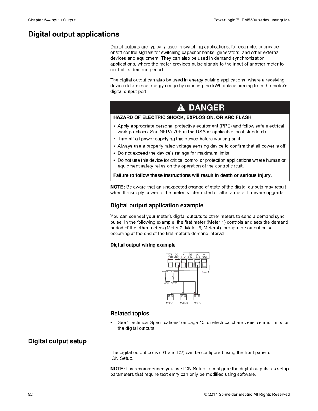
You can connect your meter’s digital outputs to other meters to send a demand sync pulse. In the following example, the first meter (Meter 1) controls and sets the demand period of the other meters (Meter 2, Meter 3, Meter 4) through the output pulse occurring at the end of the first meter’s demand interval.
Digital output wiring example
D1 D2 S1 S2
(60) (62) (40) (42) (57) (56)
< 40Vdc | < 40Vdc |
| Meter 1 |
< 20mA | < 20mA |
|
|
S1 | S1 | S1 | |
Meter 2 | Meter 3 | Meter 4 |
Related topics
•See “Technical Specifications” on page 15 for electrical characteristics and limits for the digital outputs.
Digital output setup
The digital output ports (D1 and D2) can be configured using the front panel or
ION Setup.
NOTE: It is recommended you use ION Setup to configure the digital outputs, as setup parameters that require text entry can only be modified using software.
52 | © 2014 Schneider Electric All Rights Reserved |