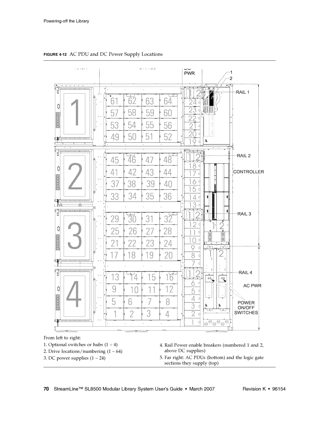
FIGURE 4-12 AC PDU and DC Power Supply Locations
From left to right:
1.Optional switches or hubs (1 – 4)
2.Drive locations/numbering (1 – 64)
3.DC power supplies (1 – 24)
4.Rail Power enable breakers (numbered 1 and 2, above DC supplies)
5.Far right: AC PDUs (bottom) and the logic gate sections they supply (top)
70 StreamLine™ SL8500 Modular Library System User's Guide • March 2007 | Revision K • 96154 |