Model GFC 7001E Family Carbon Monoxide Analyzers
Teledyne Electronic Technologies
Model GFC7001E Carbon Dioxide Analyzer
Safety Messages
This page intentionally left blank
Warranty Policy 02024D
Warranty
Coverage
Warranty Model GFC7001E Carbon Dioxide Analyzer
About this Manual
Rev Name/Description
Manual Information Model GFC7001E Carbon Dioxide Analyzer
Table of Contents
Part II Operating Instructions Basic Operation
107
149
Calibration Procedures
185
227
217
229
Maintenance Schedule & Procedures
Primer on ELECTRO-STATIC Discharge
305
List of Appendices
List of Figures
110
List of Tables
Teledyne’s Serial I/O Command Types 157
This page intentionally left blank
Part General Information
Teledyne Analytical Instruments
Introduction
GFC 7001E Family Overview
Additional Documentation
Using this Manual
Table of Contents
Basic Operation of the GFC 7001E/EM Analyzer
Advanced Features of the GFC 7001E/EM Analyzer
Maintenance Schedule and Procedures
GFC 7001E/EM Validation and Verification
Specifications
Specifications and Approvals
M 300E/300EM Basic Unit Specifications
EPA Equivalency Designation
CE Mark Compliance
Safety Compliance
TUV Designation
Emissions Compliance
This page intentionally left blank
Getting Started
GFC 7001E/EM Analyzer Layout
Rear Panel Label Function
Sample
Exhaust
IZS
Internal Layout GFC 7001E
Internal Layout GFC 7001EM with CO2 and O2 Sensor Option
Optical Bench Layout
Unpacking the GFC 7001E/EM Analyzer
General Safety Hazard
Electrical Shock Hazard
Ventilation Clearance
Ventilation Clearance
Area Minimum Required Clearance
Power Connection
Electrical Connections
PIN Analog Output Voltage Signal Current Signal
Connecting the Status Outputs
Analog Output Connector
Analog Output Connections
Rear Panel Status Label Definition
Status Output Signals
Condition
Connecting the Control Inputs
Control Input Connector Control Input Signals
Connecting to a Multidrop Network
Connecting the Serial Ports
Connecting to a LAN or the Internet
Pneumatic Connections
Span Gas
NIST-SRM Type Nominal Concentration
Pneumatic Connections to GFC 7001E/EM Basic Configuration
Sample Gas Source
Calibration Gas Sources
Input Gas Venting
Initial Operation
Exhaust Outlet
Startup
Front Panel Display during System Warm-Up
Name Color Behavior Significance
Possible Warning Messages at Start-Up
Functional Check
Initial Calibration of the GFC 7001E/EM
Interferents for CO2 Measurements
Verifying the GFC 7001E/EM Reporting Range Settings
Singl Entr
Dilution Ratio Set Up
Set CO Span Gas Concentration
To perform the zero/span calibration procedure, press
Zero/Span Calibration
GFC 7001E/EM Analyzer is now ready for operation
3. O2 Sensor Calibration Procedure
4. CO2 Sensor Calibration Procedure
Thank YOU
Frequently Asked Questions
FAQ’S
Glossary
Term Description/Definition
Data Acquisition System
As Teflon
Model GFC7001E Carbon Dioxide Analyzer
Optional Hardware and Software
Rack Mount Kits OPT 20 to OPT
Option Description Number
Carrying STRAP/HANDLE OPT
Current Loop Analog Outputs Option
Current Loop Option Installed on the Motherboard
General Information Related to ALL Valve Options
Expendables and Spares Kits Options 42A
Calibration Valves Options 50A, 50B, 50E, 50H
ZERO/SPAN Valve Option 50A
Zero/Span Valve Operating States for Option
Mode Valve Condition Sample
Internal Pneumatics OPT 50A
Zero CAL
Calibration GAS Sources
Pneumatic Set Up OPT 50A
Sample GAS Source
Span GAS
Internal Pneumatics OPT 50B
ZERO/SPAN/SHUTOFF Valve Option 50B
Zero/Span Valve Operating States for Option 50B
Input GAS Venting
Pneumatic Set Up OPT 50B
Calibration GAS Sources Span GAS
Exhaust Outlet
ZERO/SPAN Valve with Internal CO Scrubber Option 50H
Internal Pneumatics OPT 50H
Pneumatic Set Up OPT 50H
Exhaust Ouitlet
ZERO/SPAN/SHUTOFF with Internal Zero AIR Scrubber Option 50E
Internal Pneumatics OPT 50E
Pneumatic Set Up OPT 50E
60B
Communication Options
60A
60C
Ethernet Option 63A
12 GFC 7001E/EM Ethernet Card
Oxygen Sensor Option 65A
Second GAS Sensors
Ethernet + Multidrop OPT 63C
Theory of Operation Paramagnetic measurement of O2
Operation within the GFC 7001E/EM Analyzer
Pneumatic Operation of the O2 Sensor
Theory of Operation
1. CO2 Sensor Ranges and Specifications
Carbon Dioxide Sensor Option 67A
Ndir measurement of CO2
Pneumatic Operation of the CO2 Sensor
16 CO2 sensor Theory of Operation
Electronic Operation of the CO2 Sensor
17 GFC 7001E/EM Internal Pneumatics with CO2 Sensor Option
Concentration Alarm Relay Option
19 Concentration Alarm Relay
Optional Hardware and Software
Second Language Switch
Special Features
Maintenance Mode Switch
Dilution Ratio Option
Part Operating Instructions
This page intentionally left blank
Overview of Operating Modes
Basic Operation
Analyzer Operating Modes
Sample Mode
Test Functions Defined
IR source may be faulty
List of Warning Messages
Calibration Mode
Examples
Setup Mode
Setup CFG Configuration Information
Setup Acal Automatic Calibration
Password Levels
Setup Pass Password Feature
Password Level Menu Access Allowed
Basic Operation Model GFC7001E Carbon Dioxide Analyzer
Basic Operation Model GFC7001E Carbon Dioxide Analyzer
Setting the internal Clock’s Time and Day
Adjusting the Internal Clock’s Speed
GFC 7001E Family Physical range by Model
Setup Rnge Analog Output Reporting Range Configuration
Physical Range Versus Analog Output Reporting Ranges
Model Range
Analog Output Connector Pin Out
Analog Output Ranges for CO Concentration
Sngl Dual Auto
Reporting Range Modes
Range Range1 Low Range Range2 High Range
This is the default reporting range mode for the analyzer
Teledyne Analytical Instruments 101
Teledyne Analytical Instruments 102
Teledyne Analytical Instruments 103
Teledyne Analytical Instruments 104
Teledyne Analytical Instruments 105
Setup RNGE DIL Using the Optional Dilution Ratio Feature
Front Panel LED Status Indicators for iDAS
Advanced Features
Setup Idas Using the Data Acquisition System Idas
Idas Status
IDAS Channels
Idas Structure
IDAS Data Channel Properties
Default Idas Channels
Teledyne Analytical Instruments 110
Teledyne Analytical Instruments 111
Name Conc Trigger Event Atimer
Setup DAS EDIT Accessing the Idas Edit Mode
Conc ATIMER, 1
Channel No
Editing iDAS Data Channel Names
Editing iDAS Triggering Events
Editing iDAS Parameters
IDAS Data Parameter Functions
Teledyne Analytical Instruments 116
Editing Sample Period and Report Period
Report Periods in Progress When Instrument Is Powered Off
Editing the Number of Records
RS-232 Report Function
Enabling/Disabling the Holdoff Feature
Starting Date Feature
Compact Report Feature
DISABLING/ENABLING Data Channels
Remote Idas Configuration
IDAS Configuration Using Apicom
IDAS Configuration Using Terminal Emulation Programs
IDAS Configuration Through a Terminal Emulation Program
Allowed Vars Variable Description Default Values
Setup More Vars Internal Variables Vars
OFF
Teledyne Analytical Instruments 126
Setup More Diag Using the Diagnostics Functions
Accessing the Diagnostic Features
Using the GFC 7001E/EM ANALYZER’S Analog Outputs
Accessing the Analog Output Signal Configuration Submenu
Teledyne Analytical Instruments 130
Range Name Range Span Minimum Output Maximum Output
Analog Output Voltage / Current Range Selection
Analog Output Voltage Range Min/Max
Curr
Teledyne Analytical Instruments 132
Calibration of the Analog Outputs
Automatic Calibration of the Analog Outputs
Teledyne Analytical Instruments 135
Individual Calibration of the Analog Outputs
Teledyne Analytical Instruments 137
Teledyne Analytical Instruments 138
Manual Adjustment of Current Loop Output Span and Offset
Teledyne Analytical Instruments 140
100 MVDC
Voltage across Resistor for 2-20 mA Resistor for 4-20 mA
MVDC
Current Loop Output Check
Turning AN Analog Output OVER-RANGE Feature ON/OFF
Adding a Recorder Offset to AN Analog Output
Selecting a Test Channel Function for Output A4
Test Channel Description Zero Full Scale None
Teledyne Analytical Instruments 145
AIN Calibration
Setting the GFC 7001E Concentration Alarm Limits
Setup MORE Alrm Using the GAS Concentration Alarms
11 CO Concentration Alarm Default Settings
Teledyne Analytical Instruments 148
Remote Operation
Setup MORE Comm Using the ANALYSER’S Communication Ports
Comm Port Default Settings
RS-232 DTE and DCE Communication
Teledyne Analytical Instruments 150
Comm Port Baud Rate
Comm Port Communication Modes
Teledyne Analytical Instruments 153
Comm Port Testing
Machine ID
Terminal Operating Modes
Help Commands in Terminal Mode
Terminal Mode Software Commands
ESC
Teledyne’s Serial I/O Command Types
Command Syntax
ID Command CR
Command Command Type
Status Reporting
Dddhhmm Id Messagecrlf
Logon Is the default password
Comm Port Password Security
RS-232PASS=NNNNNN
Multidrop RS-232 SET UP
Location of JP2 on RS-232-Multidrop PCA Option
Tapi Analyzer
Make Sure Jumper between JP2 pins 21 Is installed
Host
Last
RS-485 Configuration of COM2
CPU RS-485 Setup
Back Panel Connector Pin-Outs for COM2 in RS-485 Mode
RX/TX RX/TX+ GND
Ethernet Card COM2 Communication Modes and Baud Rate
Remote Access VIA the Ethernet
Ethernet Status Indicators
LED Function
Configuring the Ethernet Interface Option Using Dhcp
Teledyne Analytical Instruments 166
Manually Configuring the Network IP Addresses
ON/OFF
Teledyne Analytical Instruments 169
Changing the ANALYZER’S Hostname
Minimum Requirements
Modbus Setup
Actions
Remote Access by Modem
AT Y0 &D0 &H0 &I0 S0=2 &B0 &N6 &M0 E0 Q1 &W0
Teledyne Analytical Instruments 174
General Overview of Hessen Protocol
Using the GFC 7001E/EM with a Hessen Protocol Network
Hessen Comm Port Configuration
RS-232 Communication Parameters for Hessen Protocol
Activating Hessen Protocol
Selecting a Hessen Protocol Type
Teledyne’s Hessen Protocol Response Modes
Setting the Hessen Protocol Response Mode
Mode ID Mode Description CMD
BCC
Hessen Protocol GAS List Entries
Gas List Entry Format and Definitions
Editing or Adding Hessen Gas List Entries
Deleting Hessen Gas List Entries
Operational FLAGS1
Setting Hessen Protocol Status Flags
Status Flag Name Default BIT Assignment
SPARE/UNUSED Bits
To assign or reset the status flag bit assignments, press
Instrument ID Code
Apicom Remote Control Program
Automatic ZERO/SPAN CAL/CHECK Autocal
Calibration Procedures
Before Calibration
CO Calibration Quality Analysis
Before Calibration
Required EQUIPMENT, SUPPLIES, and Expendables
Data Recording Devices
Traceability
Setup for Basic Calibration Checks and Calibration
ZERO/SPAN Calibration Checks VS. ZERO/SPAN Calibration
Teledyne Analytical Instruments 189
Performing a Basic Manual Calibration Check
Setting the Expected Span Gas Concentration
Performing a Basic Manual Calibration
Zero/Span Point Calibration Procedure
Setup for Calibration Using Valve Options
Manual Calibration with ZERO/SPAN Valves
Teledyne Analytical Instruments 194
Manual Calibration Checks with Valve Options Installed
Manual Calibration Using Valve Options
Teledyne Analytical Instruments 197
Use of Zero/Span Valve with Remote Contact Closure
Mode Name Action
Automatic ZERO/SPAN CAL/CHECK Autocal
Autocal Modes
AutoCal Attribute Setup Parameters
Attribute Action
0030
1415
Example AutoCal Sequence
Setup Acal Programming and Auto CAL Sequence
To program the example sequence shown in -4, press
Teledyne Analytical Instruments 202
AutoCal with Auto or Dual Reporting Ranges Modes Selected
DURATION30.0 Minutes
Function Minimum Value Optimum Value
CO Calibration Quality
Calibration Data Quality Evaluation
Maximum Value
Calibration of the GFC 7001E/EM’S Electronic Subsystems
Dark Calibration Test
Pressure Calibration
Flow Calibration
Electrical Test Calibration
1.1. O2 Calibration Setup
1. O2 Sensor Calibration Procedure
Calibration of Optional Sensors
Set O2 Span Gas Concentration
Activate O2 Sensor Stability Function
Teledyne Analytical Instruments 212
2.1. CO2 Calibration Setup
2. CO2 Sensor Calibration Procedure
Set CO2 Span Gas Concentration
Activate CO2 Sensor Stability Function
2.4. CO2 Zero/Span Calibration
Teledyne Analytical Instruments 216
Calibration Requirements
EPA Calibration Protocol
Calibration of Equipment General Guidelines
Data Recording Device
Calibration EQUIPMENT, SUPPLIES, and Expendables
Spare Parts and Expendable Supplies
Recommended Standards for Establishing Traceability
Matrix for Calibration Equipment & Supplies
Level 1 Calibrations Versus Level 2 Checks
Calibration Frequency
Activity Matrix for Quality Assurance Checks
Level 1 Zero and Span Calibration
Zero and Span Checks
Level 2 Zero and Span Check
Precisions Calibration
ZERO/SPAN Check Procedures
Precision Check
Calibration Audit
Auditing Procedure
Precision Calibration Procedures
Data Reduction Audit
System AUDIT/VALIDATION
Dynamic Multipoint Calibration Procedure
Linearity Test
Teledyne Analytical Instruments 225
References
Part Technical Information
Teledyne Analytical Instruments 228
Measurement Method
Theory of Operation
Measurement Fundamentals
GAS Filter Correlation
Absorption Path Lengths for GFC 7001E and GFC 7001EM
GFC Wheel
Measurement Fundamentals with GFC Wheel
Measure Reference Ratio
Effect of CO in the Sample on CO Meas & CO REF
Summary Interference Rejection
Effects of Interfering Gas on CO Meas & CO REF
Internal Pneumatic Flow Basic Configuration
Pneumatic Operation
Critical Flow Orifice Area High LOW Pressure
Flow Rate Control
Critical Flow Orifice
Spring Rings Filter
Sample Pressure Sensor
Particulate Filter
Pneumatic Sensors
Sample Flow Sensor
Electronic Operation
Overview
Board
PC 104 Bus
Mother
Sync Demod
DISK-ON-MODULE DOM
Central Processing Unit CPU
Flash Chip
Optical Bench & GFC Wheel
Temperature Control
IR Source
Segment Sensor
Sensor
Schmidt Triggers
IR Photo-Detector
Synchronous Demodulator SYNC/DEMOD Assembly
Overview
Sync Demod Sample and Hold Circuits
Signal Synchronization and Demodulation
GFC 7001E/EM Sync/Demod Block Diagram
IR Beam Passing Through
Sync/Demod Status LED’s
Photo-Detector Temperature Control
Dark Calibration Switch
Sync/Demod Status LED Activity
Heater Control
Electric Test Switch
Relay Board
GFC Wheel Motor Control
11.5.5.6. I2C Watch Dog Circuitry
LED Color Function Status When LIT Status When Unlit
Status LED’s
Relay Board Status LED’s
Sensor Inputs
Motherboard
To D Conversion
Thermistor Interface
Internal Digital I/O
Analog Outputs
External Digital I/O
Power SUPPLY/ Circuit Breaker
Power UP Circuit
Teledyne Analytical Instruments 250
Keyboard
Communication Interface
Mother
Relay Board
Keyboard
Front Panel Interface
Analyzer Status LED’s
Front Panel Status LED’s
Keypad Decoder
Display
Keyboard/Display Interface Electronics
Front Panel
Keypad Decoder
KEY-DEPRESS-DETECT Circuit
Display Data Decoder
Display Power Watch DOG
I2C Interface Chip
Display Controller
Software Operation
Adaptive Filter
Measurement Algorithm
Temperature and Pressure Compensation
Calibration Slope and Offset
Internal Data Acquisition System Idas
Teledyne Analytical Instruments 258
Maintenance Schedule
Maintenance Schedule & Procedures
Qualified Personnel
Teledyne Analytical Instruments 260
GFC 7001E/EM Maintenance Schedule
Action
MR Ratio
Date Recorded Function Operating Mode Stability
CO Meas
Pres
Function Condition Behavior
Predicting Failures Using the Test Functions
Predictive uses for Test Functions
Interpretation
Replacing the Sample Particulate Filter
Maintenance Procedures
Rebuilding the Sample Pump
Vacuum Leak Check and Pump Check
Performing Leak Checks
Pressure Leak Check
Cleaning Exterior Surfaces of the GFC 7001E/EM
Cleaning the Optical Bench
Performing a Sample Flow Check
General Troubleshooting
Troubleshooting & Repair
Suspect a Leak First
Fault Diagnosis with Warning Messages
Viewing and Clearing Warning Messages
Cannot DYN
Fault Condition Possible Causes Message
Config
Initialized
Fault Diagnosis with Test Functions
Test Functions
Pres Sample FL Samp Temp Bench Wheel BOX Temp
Test Functions Indicated Failures
Time Range Stabil CO Meas CO REF
PHT Drive Slope Offset
Diag Signal I/O Using the Diagnostic Signal I/O Function
Internal Electronic Status LED’S
CPU Status Indicator
CPU Status LED
Sync Demodulator Status LED’s
LED Function Fault Status Indicated Failures
Sync/Demod Board Status Failure Indications
Relay Board Status LED’s
Relay PCA
I2C Status LED Failure Indications
Relay Board Status LED Failure Indications
GAS Flow Problems
GFC 7001E/EM Internal GAS Flow Diagrams
Teledyne Analytical Instruments 279
Teledyne Analytical Instruments 280
Troubleshooting & Repair
Low Flow
Typical Sample GAS Flow Problems
Flow is Zero
High Flow
Displayed Flow = Warnings
Calibration Problems
Miscalibrated
Actual Flow Does Not Match Displayed Flow
Inability to Span no Span KEY
NON-REPEATABLE Zero and Span
Inability to Zero no Zero KEY
Box or Sample Temperature
Other Performance Problems
Temperature Problems
Bench Temperature
GFC Wheel Temperature
IR Photo-Detector TEC Temperature
Excessive Noise
DC Power Test Point and Wiring Color Codes
AC Mains Configuration
DC Power Supply
Name Test POINT# TP and Wire Color
DC Power Supply Acceptable Levels
KEYBOARD/DISPLAY Interface
Function Control Device
Relay Board Control Devices
Socket
Sync/Demodulator Assembly
Sensor Assembly
Electrical Test
Opto Pickup Board Nominal Output Frequencies
Opto Pickup Assembly
GFC Wheel Drive
TP2 TP4
Pressure/Flow Sensor Assembly
Full Scale Output of Voltage Range
13.5.7.1. A/D Functions
Test Channel / Analog Outputs Voltage
Step Nominal Output Voltage
Analog Outputs Current Loop
Output Range Nominal Output Values Step Current
12 Status Outputs Check
Status Outputs
PIN Left to Right Status
RS-232 Communications
General RS-232 Troubleshooting
Control Inputs Remote Zero, Span
Troubleshooting Analyzer/Modem or Terminal Operation
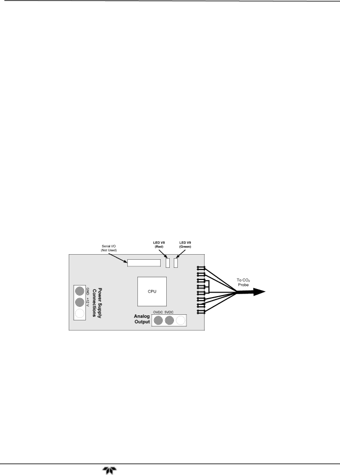
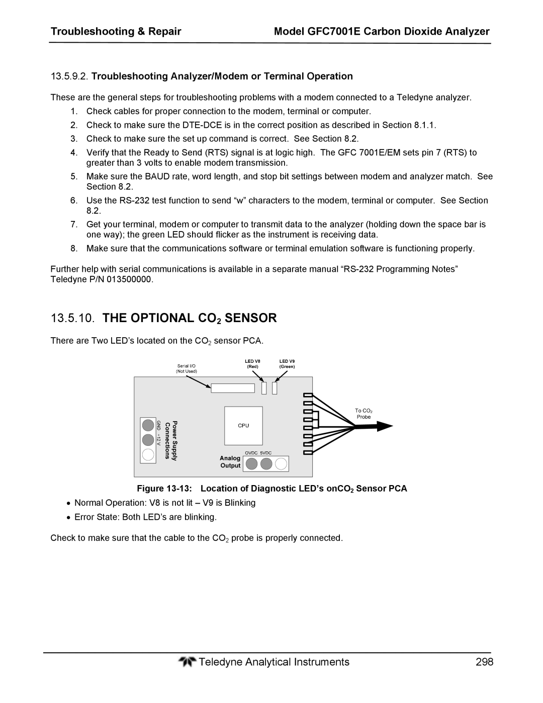
Optional CO2 Sensor
Repair Procedures
Repairing Sample Flow Control Assembly
15 Opening the GFC Wheel Housing
REMOVING/REPLACING the GFC Wheel
Teledyne Analytical Instruments 301
Checking the Sync/Demodulator Circuit Gain
18 Removing the GFC Wheel
Adjusting the Sync/Demodulator, Circuit Gain
Adjustment Made Here
DISK-ON-MODULE Replacement Procedure
Technical Assistance
Static Generation Voltages for Typical Activities
Primer on ELECTRO-STATIC Discharge
HOW Static Charges are Created
Means of Generation
Damage Susceptibility Voltage
HOW ELECTRO-STATIC Charges Cause Damage
Sensitivity of Electronic Devices to Damage by ESD
Device Range
Basic Principles of Static Control
Common Myths about ESD Damage
General Rules
Teledyne Analytical Instruments 308
Working at the Instrument Rack
Working at an Anti-ESD Work Bench
Opening Shipments from Teledyne’ Customer Service
Transferring Components from Rack to Bench and Back
Packing Components for Return to Teledyne’s Customer Service
ESD Hazard
Teledyne Analytical Instruments 312
Bench Temp WARNING, 49, 88, 182, 269 Bench Temperature
Analog CAL WARNING, 49, 88 Analog Inputs
Index
Teledyne Analytical Instruments 315
Internal Span Gas Generator
Pnuntc
Relay Board WARN, 49, 88, 269 relay PCA
Pressure Span Inlet
Rear Board not DET, 49, 88, 182
Calibration
Interactive Mode
Span2 Inlet, 32 Specifications, 25
Source WARNING, 49, 88
Vent Outlet
Teledyne Analytical Instruments 320
Teledyne Analytical Instruments 321