Component Testing
For accurate resistance and/or continuity checks, elec- trically disconnect the component being tested from the circuit (e.g. unplug the ignition switch connector before doing a continuity check).
NOTE: For engine component testing information, see the Kubota Workshop Manual, Diesel Engine,
![]() CAUTION
CAUTION
When testing electrical components for continu- ity with a multimeter (ohms setting), make sure that power to the circuit has been disconnected.
Ignition Switch
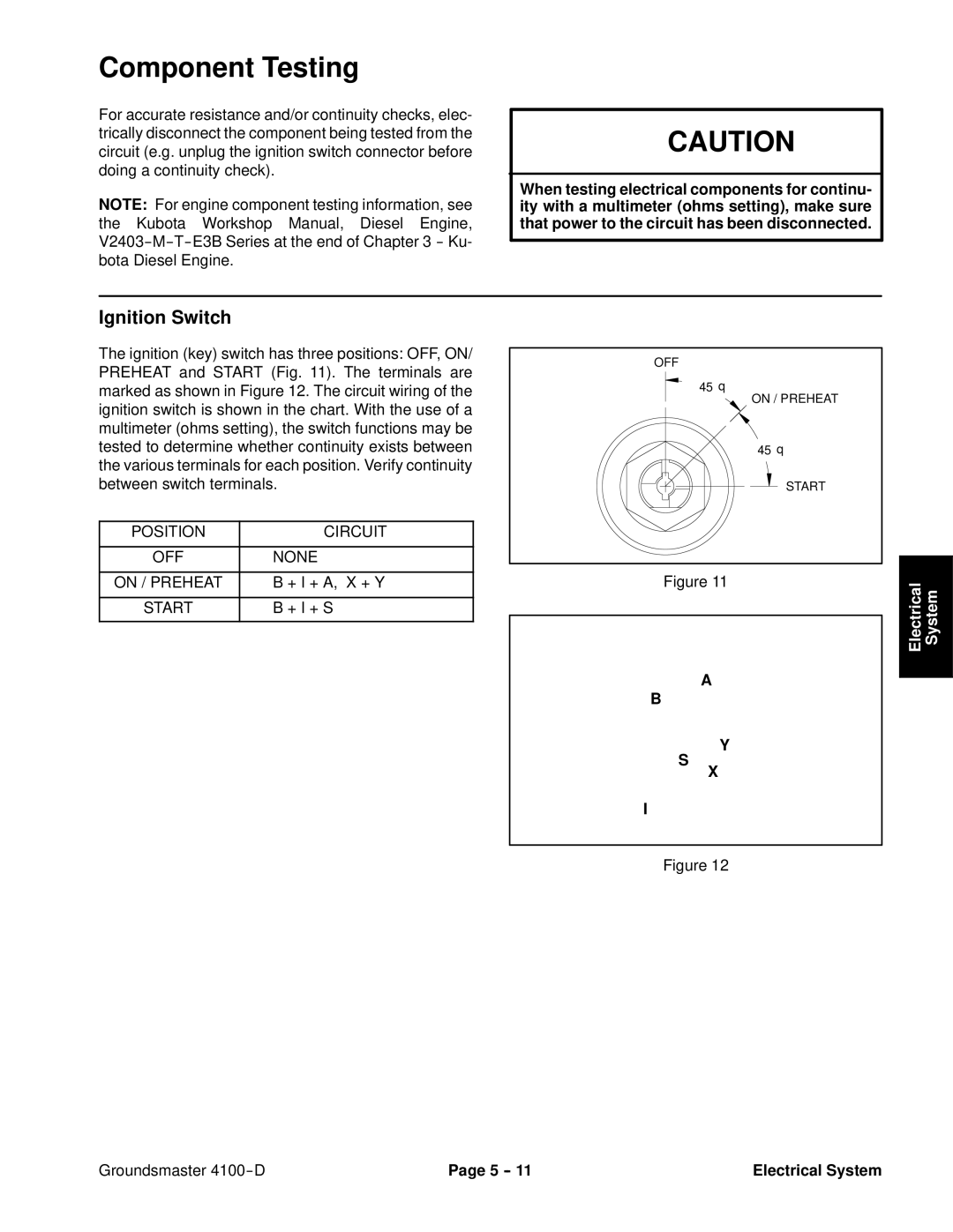
The ignition (key) switch has three positions: OFF, ON/ PREHEAT and START (Fig. 11). The terminals are marked as shown in Figure 12. The circuit wiring of the ignition switch is shown in the chart. With the use of a multimeter (ohms setting), the switch functions may be tested to determine whether continuity exists between the various terminals for each position. Verify continuity between switch terminals.
POSITION | CIRCUIT |
|
|
OFF | NONE |
|
|
ON / PREHEAT | B + I + A, X + Y |
|
|
START | B + I + S |
|
|
OFF
45 °
ON / PREHEAT
45 °
START
Figure 11
A
Electrical System
B
S
I
Y
X
Figure 12
Groundsmaster | Page 5 | Electrical System |