Removal (Fig. 1)
1.Position machine on a clean, level surface. Lower cutting deck, stop engine, engage parking brake and re- move key from the ignition switch.
NOTE: Removal of clevis pins from deck and
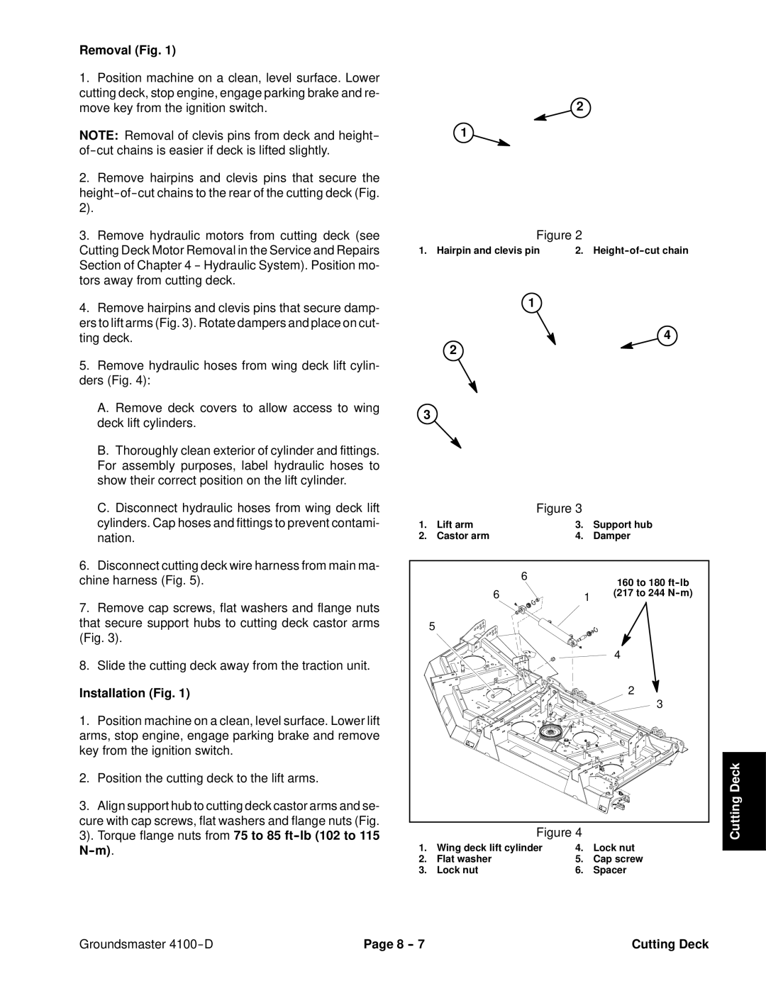
2.Remove hairpins and clevis pins that secure the
3.Remove hydraulic motors from cutting deck (see Cutting Deck Motor Removal in the Service and Repairs Section of Chapter 4
4.Remove hairpins and clevis pins that secure damp- ers to lift arms (Fig. 3). Rotate dampers and place on cut- ting deck.
5.Remove hydraulic hoses from wing deck lift cylin- ders (Fig. 4):
A.Remove deck covers to allow access to wing deck lift cylinders.
B.Thoroughly clean exterior of cylinder and fittings. For assembly purposes, label hydraulic hoses to show their correct position on the lift cylinder.
C.Disconnect hydraulic hoses from wing deck lift cylinders. Cap hoses and fittings to prevent contami- nation.
6.Disconnect cutting deck wire harness from main ma- chine harness (Fig. 5).
7.Remove cap screws, flat washers and flange nuts that secure support hubs to cutting deck castor arms (Fig. 3).
8.Slide the cutting deck away from the traction unit.
Installation (Fig. 1)
1.Position machine on a clean, level surface. Lower lift arms, stop engine, engage parking brake and remove key from the ignition switch.
2.Position the cutting deck to the lift arms.
3.Align support hub to cutting deck castor arms and se- cure with cap screws, flat washers and flange nuts (Fig. 3). Torque flange nuts from 75 to 85
2
1
Figure 2
1. Hairpin and clevis pin | 2. |
1
4
2
3
|
| Figure 3 |
|
1. | Lift arm | 3. | Support hub |
2. | Castor arm | 4. | Damper |
| 6 | 160 to 180 |
|
| |
6 | 1 | (217 to 244 |
5 |
|
|
|
| 4 |
|
| 2 |
|
| 3 |
| Figure 4 | Cutting Deck |
1. | Wing deck lift cylinder | 4. | Lock nut |
2. | Flat washer | 5. | Cap screw |
3. | Lock nut | 6. | Spacer |
Groundsmaster | Page 8 | Cutting Deck |