PTO Switch
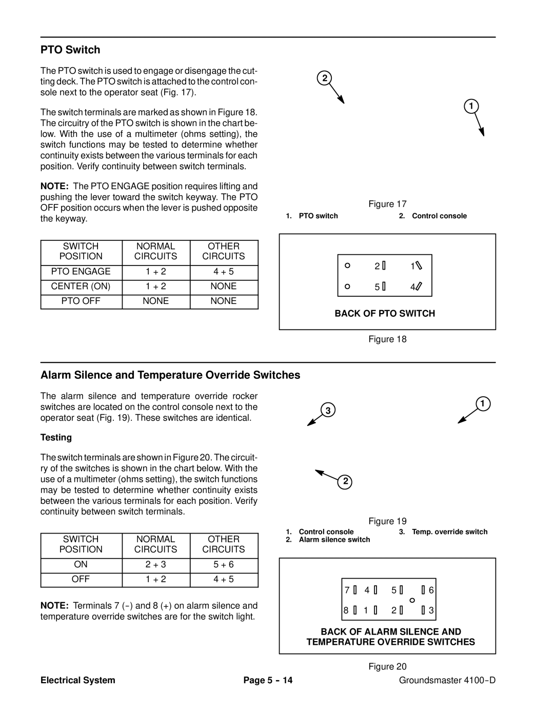
The PTO switch is used to engage or disengage the cut- ting deck. The PTO switch is attached to the control con- sole next to the operator seat (Fig. 17).
The switch terminals are marked as shown in Figure 18. The circuitry of the PTO switch is shown in the chart be- low. With the use of a multimeter (ohms setting), the switch functions may be tested to determine whether continuity exists between the various terminals for each position. Verify continuity between switch terminals.
NOTE: The PTO ENGAGE position requires lifting and pushing the lever toward the switch keyway. The PTO OFF position occurs when the lever is pushed opposite the keyway.
SWITCH | NORMAL | OTHER |
POSITION | CIRCUITS | CIRCUITS |
|
|
|
PTO ENGAGE | 1 + 2 | 4 + 5 |
|
|
|
CENTER (ON) | 1 + 2 | NONE |
|
|
|
PTO OFF | NONE | NONE |
|
|
|
2
1
| Figure 17 |
1. PTO switch | 2. Control console |
21
54
BACK OF PTO SWITCH
Figure 18
Alarm Silence and Temperature Override Switches
The alarm silence and temperature override rocker switches are located on the control console next to the operator seat (Fig. 19). These switches are identical.
Testing
3
1
The switch terminals are shown in Figure 20. The circuit- ry of the switches is shown in the chart below. With the use of a multimeter (ohms setting), the switch functions may be tested to determine whether continuity exists between the various terminals for each position. Verify continuity between switch terminals.
SWITCH | NORMAL | OTHER |
POSITION | CIRCUITS | CIRCUITS |
|
|
|
ON | 2 + 3 | 5 + 6 |
|
|
|
OFF | 1 + 2 | 4 + 5 |
|
|
|
NOTE: Terminals 7
![]() 2
2
|
| Figure 19 |
1. | Control console | 3. Temp. override switch |
2. | Alarm silence switch | |
7 | 4 | 5 | 6 |
8 | 1 | 2 | 3 |
BACK OF ALARM SILENCE AND
TEMPERATURE OVERRIDE SWITCHES
|
| Figure 20 |
Electrical System | Page 5 | Groundsmaster |