Installation (Fig. 13)
1.Position spindle on cutting deck noting orientation of grease fitting (Fig. 15). Secure spindle assembly to deck with removed fasteners.
2.Install cutting blade,
3.Slowly rotate cutting blades to verify that blades do not contact any deck component(s).
4.Install drive belt and adjust belt tension (see Idler As- sembly Installation in this section).
5.If drive spindle was removed, install hydraulic motor to cutting deck (see Cutting Deck Motor Installation in the Service and Repairs Section of Chapter 4
6.Install belt covers to cutting deck.
1
2
1
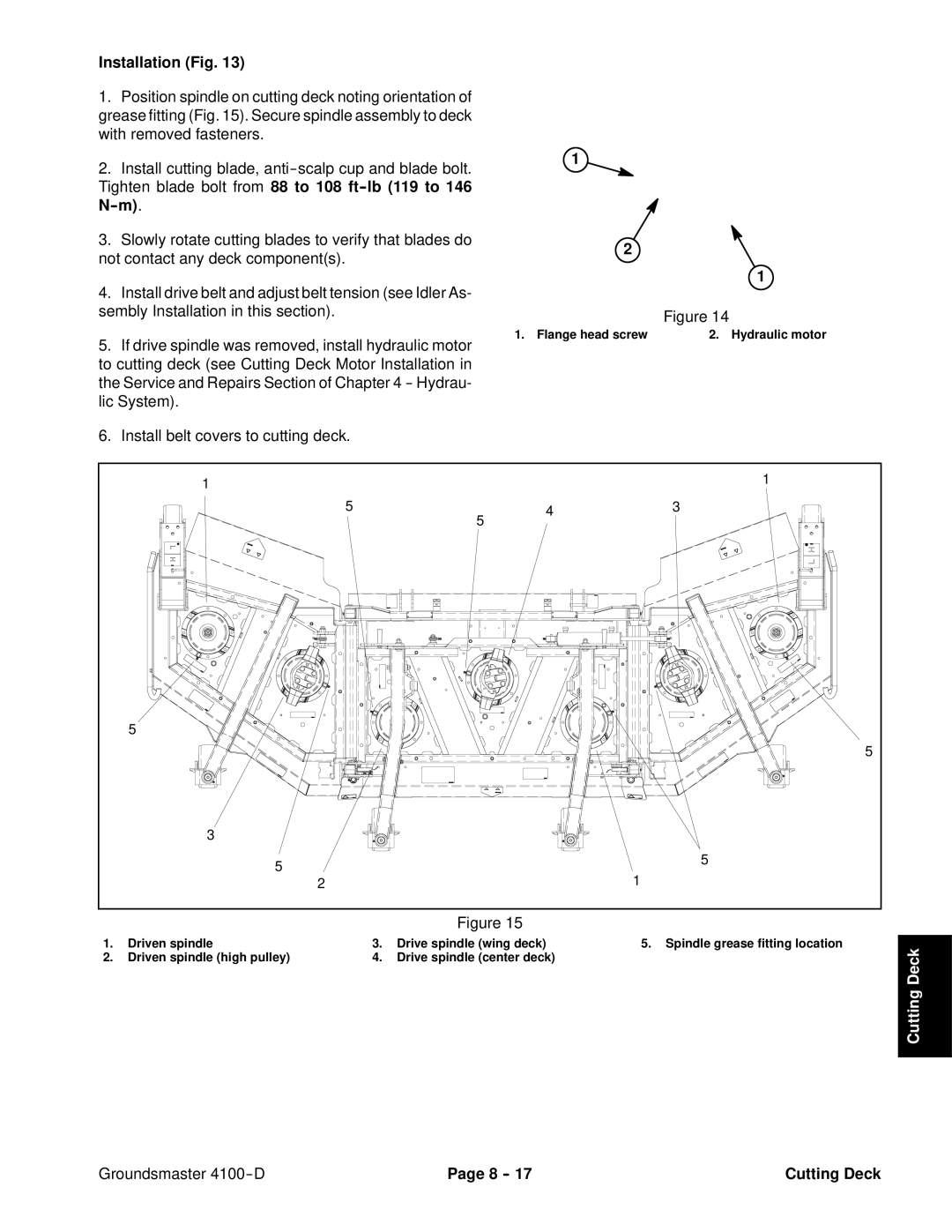
Figure 14
1. Flange head screw | 2. Hydraulic motor |
1 |
|
| 1 |
|
|
| |
5 | 5 | 4 | 3 |
|
|
| |
5 |
|
|
|
|
|
| 5 |
3 |
|
|
|
5 |
|
| 5 |
|
| 1 | |
2 |
|
|
Figure 15
1. | Driven spindle | 3. | Drive spindle (wing deck) | 5. Spindle grease fitting location | DeckCutting | |
2. | Driven spindle (high pulley) | 4. | Drive spindle (center deck) |
| ||
|
| |||||
|
|
|
|
|
| |
|
|
|
|
|
|
Groundsmaster | Page 8 | Cutting Deck |