Cooling Fan Switch
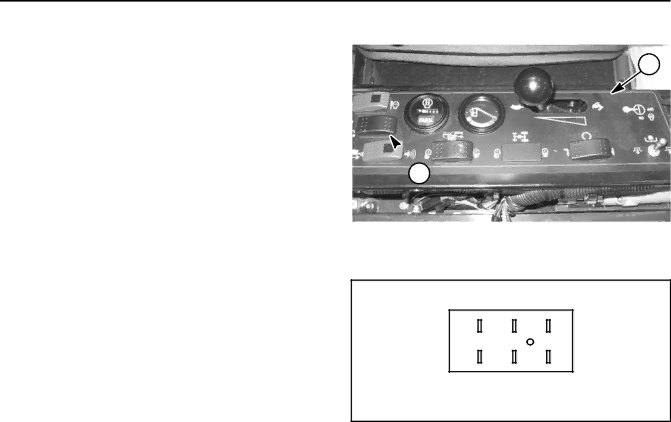
The cooling fan switch is used to control the operation of the hydraulic cooling fan and is located on the control console (Fig. 23). This switch has three (3) positions: Reverse, Auto and Forward.
When the cooling fan switch is in the normal Auto posi- tion, cooling fan operation is controlled by the
If the operator depresses the cooling fan switch to the Reverse position, a fan reverse cycle that is controlled by the
If the cooling fan switch is placed in the Forward posi- tion, the engine cooling fan will run only in the forward direction.
Testing
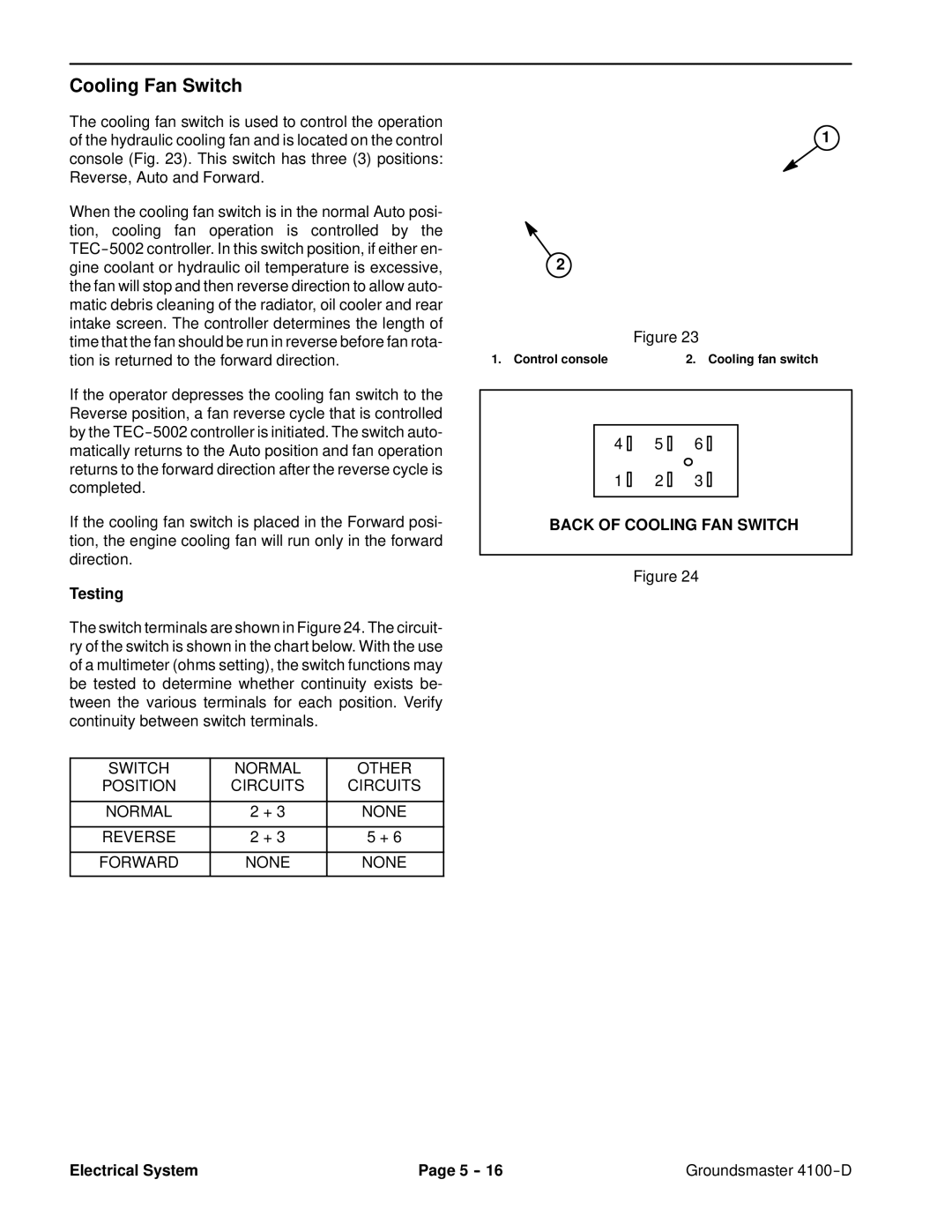
The switch terminals are shown in Figure 24. The circuit- ry of the switch is shown in the chart below. With the use of a multimeter (ohms setting), the switch functions may be tested to determine whether continuity exists be- tween the various terminals for each position. Verify continuity between switch terminals.
SWITCH | NORMAL | OTHER |
POSITION | CIRCUITS | CIRCUITS |
|
|
|
NORMAL | 2 + 3 | NONE |
|
|
|
REVERSE | 2 + 3 | 5 + 6 |
|
|
|
FORWARD | NONE | NONE |
|
|
|
1
![]() 2
2
| Figure 23 |
1. Control console | 2. Cooling fan switch |
4 | 5 | 6 |
1 | 2 | 3 |
BACK OF COOLING FAN SWITCH
Figure 24
Electrical System | Page 5 | Groundsmaster |
